Spiral stirrup fixing device

A technology of spiral stirrups and fixing devices, applied in the directions of packaging, transportation and packaging, external frame, etc., can solve the problems of time-consuming, labor-intensive, low work efficiency, inconvenience, etc., to reduce production costs, improve production efficiency, and save labor. Effect

Inactive Publication Date: 2012-01-04
DALIAN GREAT GOLDEN HORSE INFRASTRUCTURE
View PDF6 Cites 1 Cited by
  • Summary
  • Abstract
  • Description
  • Claims
  • Application Information

AI Technical Summary

Problems solved by technology

Due to the elastic effect of the spiral stirrup itself, it must be fixed when laying the reinforcement. The traditional craft is to bind it with iron wires. This method is not only time-consuming and laborious, but also extremely inconvenient in the subsequent reinforcement deployment. The work efficiency is low and it does not conform to industrialization. production requirements

Method used


Image

  • Spiral stirrup fixing device
  • Spiral stirrup fixing device

Examples


Embodiment 1

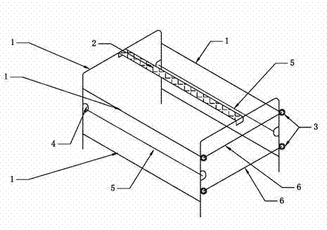
[0012] Such as figure 1 As shown, a spiral stirrup fixing device includes a main frame 1 of the device, and the main frame 1 of the device is a U-shaped groove structure, that is, a U-shaped groove-shaped skeleton is made of steel bars and other materials, and the U-shaped groove opening is opened when in use. Orientation is used against the spiral stirrup. The spiral stirrup fixing device also includes a stirrup clamping device, the stirrup clamping device is a stirrup fixing intubation tube 4 fixed on the device main frame 1 and a splint 5 that can pass through the stirrup fixing insertion tube 4, and the stirrup fixing The intubation tube 4 is arranged on two vertical sides on the same side elevation of the device main frame 1, and is symmetrically distributed, and the splint 5 passes therethrough, and the effect of the splint 5 is to clamp the spiral stirrup.

[0013] The spiral stirrup fixing device also includes a main rib positioning device, and the main rib positionin...

Embodiment 2

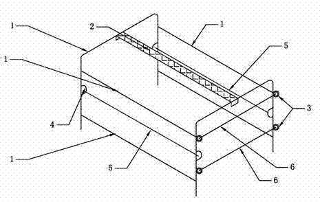
[0017] A spiral stirrup fixing device, comprising a main frame 1 of the device, the main frame 1 of the device is a U-shaped groove structure, that is, a U-shaped groove-shaped skeleton is made of steel bars and other materials, and the opening direction of the U-shaped groove faces the Spiral stirrups are used. The spiral stirrup fixing device also includes a stirrup clamping device, the stirrup clamping device is a stirrup fixing intubation tube 4 fixed on the device main frame 1 and a splint 5 that can pass through the stirrup fixing insertion tube 4, and the stirrup fixing The intubation tube 4 is arranged on two vertical sides on the same side elevation of the device main frame 1, and is symmetrically distributed, and the splint 5 passes therethrough, and the effect of the splint 5 is to clamp the spiral stirrup.

[0018] The spiral stirrup fixing device also includes a sign 2 arranged on the top of the main frame 1 of the device. The signboard 2 is used to indicate the ...

Embodiment 3

[0022] A spiral stirrup fixing device, comprising a main frame 1 of the device, the main frame 1 of the device is a U-shaped groove structure, that is, a U-shaped groove-shaped skeleton is made of steel bars and other materials, and the opening direction of the U-shaped groove faces the Spiral stirrups are used. The spiral stirrup fixing device also includes a stirrup clamping device, the stirrup clamping device is a stirrup fixing intubation tube 4 fixed on the device main frame 1 and a splint 5 that can pass through the stirrup fixing insertion tube 4, and the stirrup fixing The intubation tube 4 is arranged on two vertical sides on the same side elevation of the device main frame 1, and is symmetrically distributed, and the splint 5 passes therethrough, and the effect of the splint 5 is to clamp the spiral stirrup.

[0023] The use of the spiral stirrup fixing device, after the spiral stirrup is wound into shape, on the spiral stirrup winding drum, first put the U-shaped mo...


PUM


Abstract

The invention discloses a spiral stirrup fixing device, and relates to the field of building construction. The spiral stirrup fixing device comprises a main device frame (1), wherein the main device frame (1) has a U-shaped groove structure; and the spiral stirrup fixing device also comprises a stirrup clamping device, wherein the stirrup clamping device comprises a stirrup fixing insertion pipe (4) fixed on the main device frame (1) and a clamping plate (5) capable of passing through the stirrup fixing insertion pipe (4). Through the spiral stirrup fixing device, spiral stirrups can be normally and regularly bound together; and in the transport and distribution process, the spiral stirrups are not crossed or disordered, so that manpower is saved, the production efficiency is improved, and the production cost is greatly reduced.

Description

technical field [0001] The invention relates to the field of building construction, in particular to a spiral stirrup fixing device during the manufacturing process of prestressed square piles. Background technique [0002] With the development of economy and technology, great changes have taken place in the construction industry, especially the appearance of prestressed square piles. With the development and demand of the construction market, the supply of prestressed square piles has been in short supply, but due to the limitation of processing methods, its output has not been greatly increased. Engineers and technicians have been working hard on the large-scale production of prestressed square piles, hoping to improve the large-scale production of prestressed square piles. Due to the elastic effect of the spiral stirrup itself, it must be fixed when laying the reinforcement. The traditional craft is to bind it with iron wires. This method is not only time-consuming and l...

Claims


Application Information

Patent Timeline
Patent Type & Authority Applications(China)
IPC IPC(8): B65D61/00
Inventor 徐良酉
Owner DALIAN GREAT GOLDEN HORSE INFRASTRUCTURE
Why Eureka
Try Eureka