Method and apparatus for dampening waves in a wave pool

一种波浪、阻尼室的技术,应用在波浪池领域,能够解决冲浪操作难进行、可冲浪波浪质量下降、财产资产价值减小等问题

Active Publication Date: 2012-01-04
托马斯·J·勒希特费尔德 +2
View PDF6 Cites 18 Cited by
  • Summary
  • Abstract
  • Description
  • Claims
  • Application Information

AI Technical Summary

Problems solved by technology

Taking this reflection into account, countercurrents can be created, which can lead to a significant loss of surfable wave quality, which can make surfing maneuvers more difficult
[0006] A third corollary disadvantage associated with the formation of rip currents and wave reflections is the consequent reduction in pool production asset value, which may stem from having to reduce the frequency of waves in an attempt to reduce undesired motion and features.
Thus, a related disadvantage that may arise from the use of large crossing wave pools is that the frequency of wave generation may be reduced, i.e., for example, to one wave per minute to over ninety seconds, in which case the property's Property value also decreased
[0007] A fourth disadvantage is that such crossover wave pools tend to be larger and inherently more expensive to build
Unfortunately, this solution has the adverse effect of forcing spectators (who are usually seated on bleachers or covered stands located immediately behind the beach and above the waterline) to stay away from the waves, which can make it difficult for spectators to see and enjoy Wave and Surf Action

Method used


Image

  • Method and apparatus for dampening waves in a wave pool
  • Method and apparatus for dampening waves in a wave pool
  • Method and apparatus for dampening waves in a wave pool

Examples


Embodiment 1

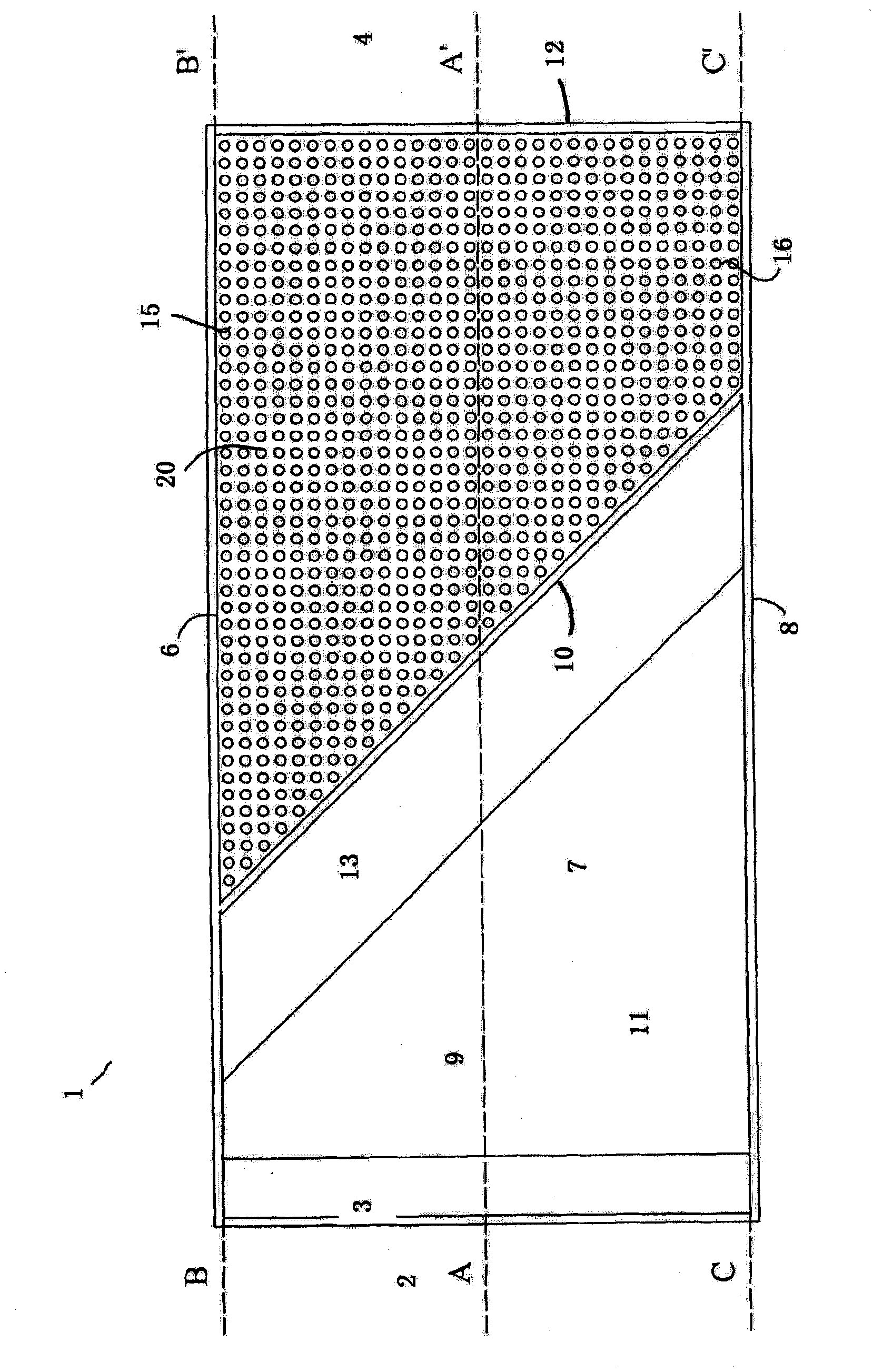
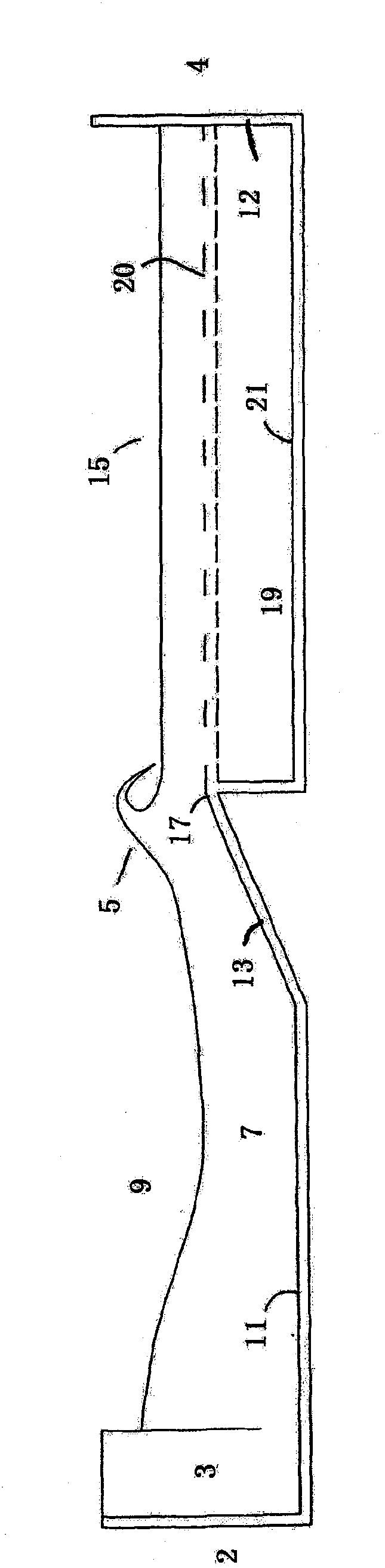
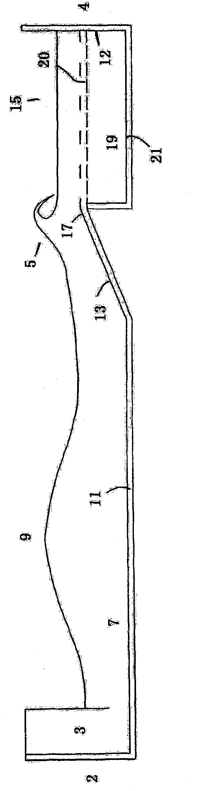
[0097] Example 1: When it is desired to generate a drum-type wave with a height of three to eight feet and a period of about fifteen seconds, the preferred depth of the horizontal floor 11 or pool depth is generally about three times the wave height. Accordingly, if the desired wave height is three feet, the preferred pool depth would be nine feet, and likewise, if the desired wave height is eight feet, the preferred pool depth would be twenty-four feet. These represent preferred minimum and maximum pool depth values ​​d for each environment 底面 .

[0098] The preferred inclination of the oblique section 13 for generating drum-type waves with a period of fifteen seconds, which extends upwards from the horizontal base 11 , is preferably between about 5% and 10%. At the same time, the oblique section 13 preferably terminates at the crushing depth, and the rising floor 20 extends substantially horizontally from the oblique section 13 towards the end wall 12 , preferably at the sa...

Embodiment 2

[0101] Example 2: When it is desired to generate overflow-type waves with a height of three to eight feet and a period of about eight seconds, the preferred depth of the horizontal floor 11 or pool depth is generally about three times the wave height. Accordingly, if the desired wave height is three feet, the preferred pool depth would be nine feet, and likewise, if the desired wave height is eight feet, the preferred pool depth would be twenty-four feet. These represent preferred minimum and maximum pool depth values ​​d for each environment 底面 . Also, to generate overflow type waves, the preferred slope of the oblique section 13, which extends upward from the horizontal bottom surface 11, is preferably 5% or less. At the same time, as already mentioned, the oblique section 13 preferably ends at the crushing depth, wherein the top 17 and the rising floor 20 of the oblique section 13 are also located at the same height.

[0102] In this embodiment, it has been determined fro...

Embodiment 3

[0105] Example 3: In another example, when it is desired to generate drum type waves five feet high with a period of fifteen seconds, in a wave pool with a horizontal floor 11 that is fifteen feet deep, the following applies:

[0106] The slope of the inclined section 13 is preferably about 10% in order to be able to generate a drum-shaped wave. Also, in this example, based on the above factors, the preferred depth of crushing was determined to be about three feet. Accordingly, in this embodiment, with a wave height of five feet, the preferred pool depth is about fifteen feet, and the preferred submersion depth of the raised floor 20 will be about three feet. It can be seen that if the value is much greater than three feet, the waves will not break properly, while if the value is much less than three feet, there is a danger of reverse flow.

[0107] It has also been determined that the ideal depth of the wave damping chamber 19 below the raised floor 20 is about three times t...


PUM


Abstract

Disclosed is a method and apparatus for dampening waves preferably comprising a wave pool having two portions, a first wave forming portion with an inclined section oriented obliquely relative to the travel direction of the waves that causes the waves to begin breaking, and a second wave dampening portion having a relatively deep solid chamber floor and a raised perforated floor above it for dampening the waves after they begin to break. The properties of the raised floor, including its porosity, its depth (relative to the chamber depth), and the characteristics of the waves to be dampened, including the wave height and shape, are taken into account in designing a dampening system that substantially dissipates the waves, which in turn, reduces wave reflections and rip currents that can interfere with the next oncoming waves, and thereby, help to maintain quality surfing waves at high frequencies without increasing pool size.

Description

technical field [0001] The present invention relates to the field of wave pools, and in particular to wave pools that generate large surf-grade waves that are damped so as to be able to increase the capacity per available unit of space. Background technique [0002] In recent years, wave pools have become increasingly popular in water theme parks. A wave pool is a man-made body of water in which waves are formed that closely resemble those in the ocean. Wave pools typically have a wave generating machine at one end and an artificial "beach" with a slope at the other, where the wave generating machine generates periodic waves that travel from one end to the other. The floor of the pool near the beach end preferably slopes upwards so that the sloped floor "breaks" the waves on the beach as they approach. [0003] In some cases, the size and power of wave pools have been increased so that they can be used intermittently as "crossover" wave pools that produce large surf-grade ...

Claims


Application Information

Patent Timeline
Patent Type & Authority Applications(China)
IPC IPC(8): A47K3/10
CPCE04H4/0006A63B69/0093A63G31/007Y02E10/30
Inventor 托马斯·J·勒希特费尔德亨德里克·迪尔克·凡·埃廷格迪尔克·巴斯滕霍夫
Owner 托马斯·J·勒希特费尔德
Why Eureka
Try Eureka