

Novel hearth brick for annealing electric furnace
A technology of laying bricks and annealing, which is applied to electric furnace heating, furnace and furnace components, etc., can solve the problems of easy falling off of electric furnace wires, large use of bricks, and many joints of bricks, so as to improve the overall thermal insulation effect and reduce electric energy. consumption, avoid accidents
Inactive Publication Date: 2012-01-11
曹晶晶
View PDF0 Cites 0 Cited by
- Summary
- Abstract
- Description
- Claims
- Application Information
AI Technical Summary
Problems solved by technology
[0003] The purpose of the present invention is to provide an annealing electric furnace hearth brick, which overcomes the defects of large usage of bricks, inconvenient installation and maintenance, many joints between bricks, and reduction of the overall heat preservation performance of the furnace. There is no protruding flange at the end of the brick, and the electric furnace wire is easy to fall off. The invention provides a new annealing electric furnace hearth brick. Using this brick can effectively avoid the above defects
Method used
View moreImage
Smart ImageViewing Examples

Examples
Embodiment Construction
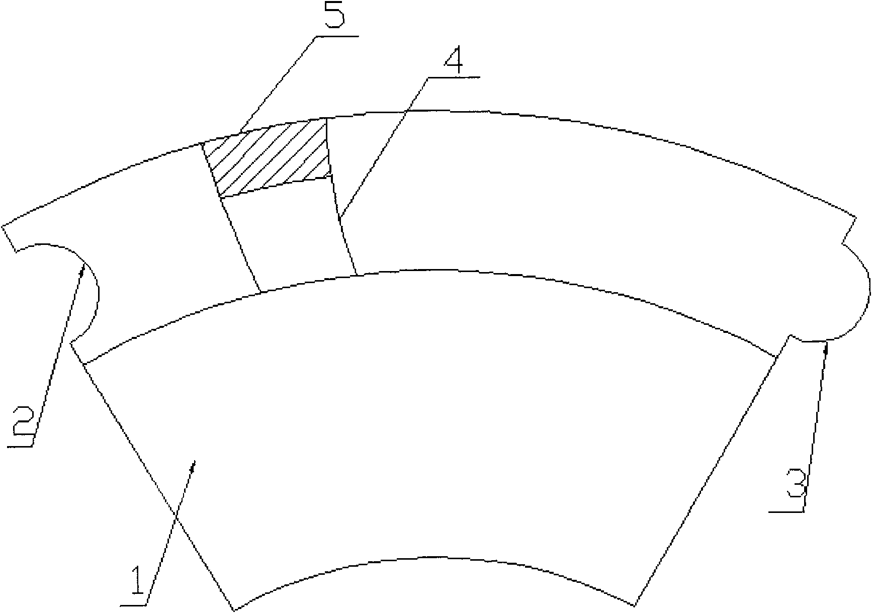
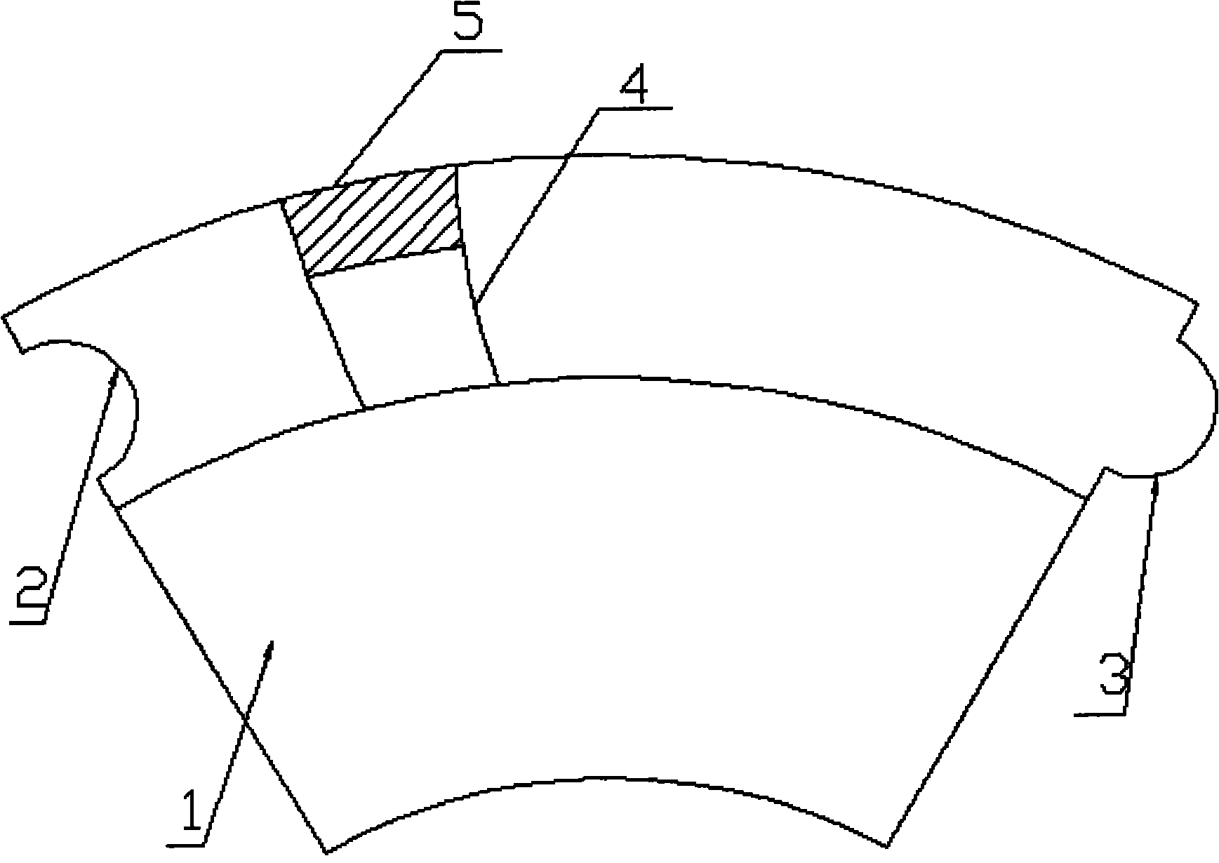
[0009] There is a brick resting body (1) in the hearth of the annealing electric furnace, and the fan-shaped included angle of the brick resting body (1) is made into an angle of 60°, and there are convex arc grooves (3) and concave arc grooves (3) on the raised parts of the two sides of the fan-shaped respectively. The two grooves of the arc groove (2) should be fastened with the grooves on the adjacent bricks. In the outer circle direction of the brick (1), a flange (5) is arranged along the outer circle direction. Inside, make an inward semicircular groove (4).
Login to View More PUM
 Abstract
The invention relates to a novel hearth brick for an annealing electric furnace. The hearth brick comprises a brick body, a concave arc groove, a convex arc groove, an inward semi-circle groove and a flange. The hearth brick for the annealing electric furnace has the brick body; an included angle of 60 DEG is formed by a fan-shaped included angle of the brick body; the convex and the concave arc grooves are respectively disposed on the convex parts at both fan-shaped side faces and are rightly buckled with grooves on adjacent bricks; the flange is arranged along a circumference direction of the brick; and the inward semi-circle groove is fabricated at the inner side of the flange.
Description
technical field [0001] The invention relates to a furnace brick, in particular to a novel annealing electric furnace furnace brick, which belongs to the technical field of industrial heat treatment equipment. Background technique [0002] Electric annealing furnace is the main heating equipment used in the heat treatment process. In all heat treatment electric annealing furnaces at present, the bricks carrying the electric furnace wire are all small in size, similar to rectangular parallelepiped bricks. The outstanding problems of this kind of bricks are: along the circumference The layout of the furnace needs to be trimmed, which increases the time taken for equipment installation and maintenance. At the same time, the joints are not tight. Due to the small size, the amount of bricks used is correspondingly increased, so the joints also increase accordingly. The overall thermal insulation performance of the furnace is poor, which increases the consumption of energy. Becaus...
Claims
Login to View More Application Information
Patent Timeline
 Patent Type & Authority Applications(China)
IPC IPC(8): C21D1/26F27D1/04F27D11/02
Inventor 曹晶晶
Owner 曹晶晶