Diaphragm wall and construction method thereof

An underground diaphragm wall and construction method technology, which is applied in excavation, artificial islands, water conservancy projects, etc., can solve the problems of limited applicability, need for further verification, and lack of waterproof and anti-seepage functions, so as to improve the waterproof performance and ensure the groove wall Stability, effects of coordinating differential settlement

Inactive Publication Date: 2012-01-11
CCCC THIRD HARBOR CONSULTANTS
View PDF7 Cites 49 Cited by
  • Summary
  • Abstract
  • Description
  • Claims
  • Application Information

AI Technical Summary

Problems solved by technology

[0007] The three-in-one underground diaphragm wall in this invention refers to the underground diaphragm wall that integrates soil retaining, waterproofing and load-bearing, but its waterproof function is only limited to the foundation pit construction stage, and the underground diaphragm wall built according to its construction method is in the structural use stage. The waterproof effect need

Method used


Image

  • Diaphragm wall and construction method thereof
  • Diaphragm wall and construction method thereof
  • Diaphragm wall and construction method thereof

Examples


Embodiment Construction

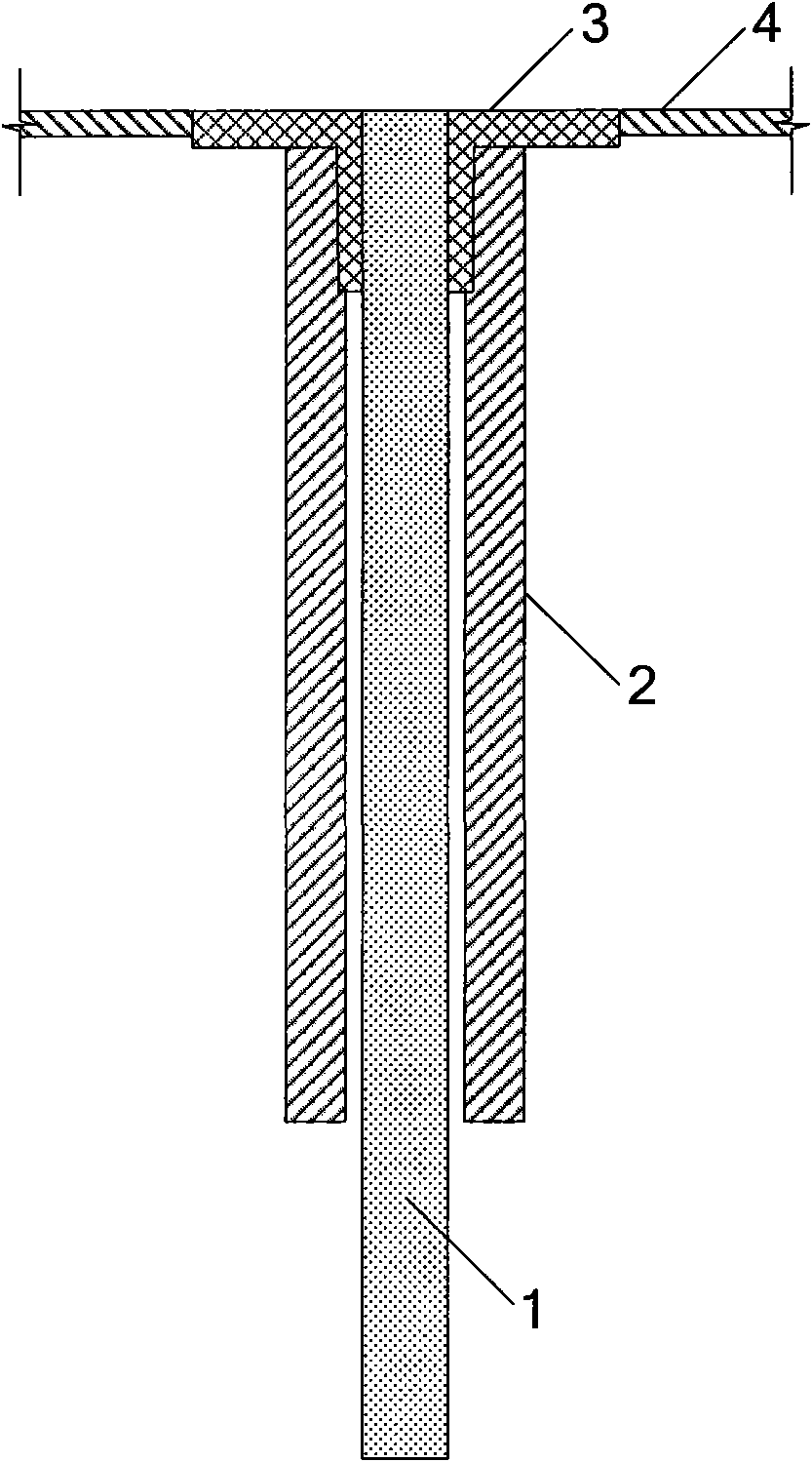
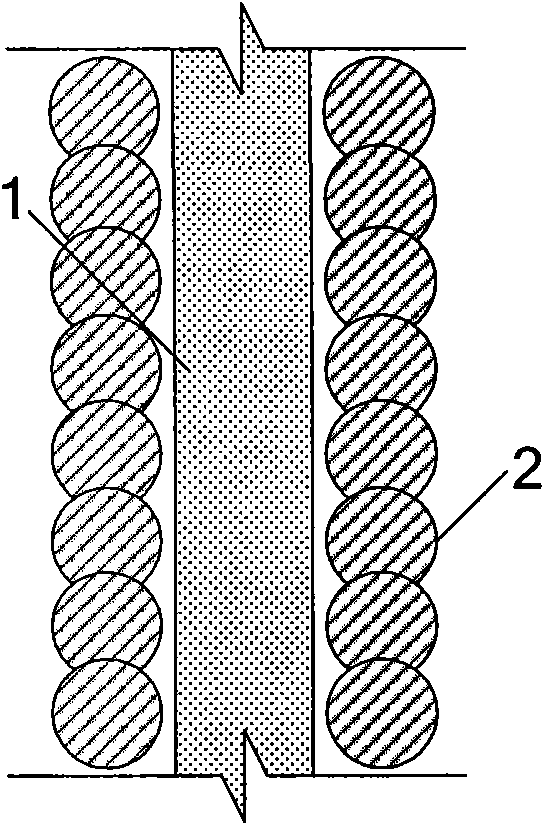
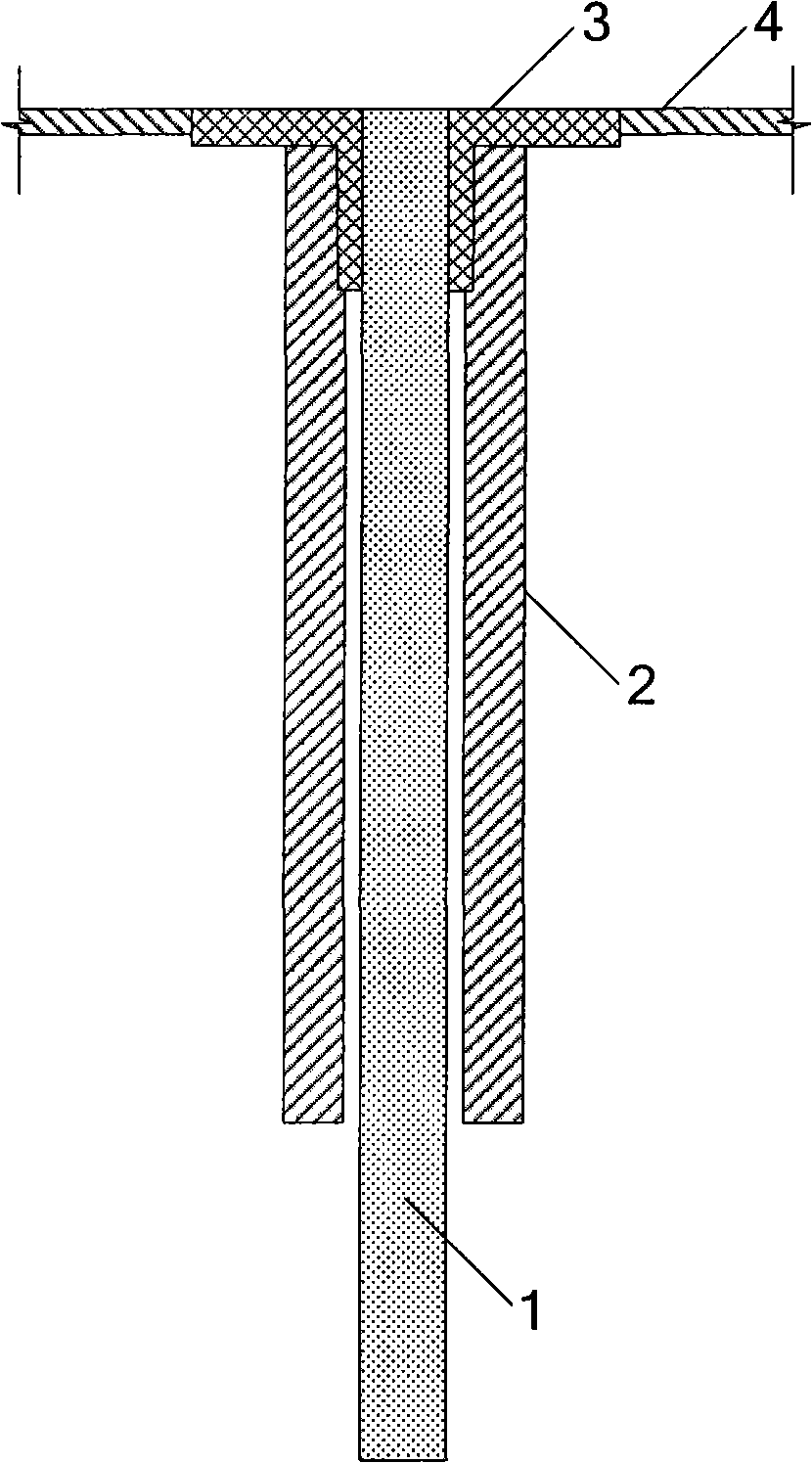
[0036] See figure 1 , is the underground diaphragm wall involved in the present invention, comprising an underground diaphragm wall body 1 , cement-soil mixing pile 2 , guide wall 3 and rigid floor 4 . There are multiple cement-soil mixing piles 2, symmetrically arranged on both sides of the underground diaphragm wall body 1, and the cement-soil mixing piles 2 are engaged. The guide wall 3 is a monolithic reinforced concrete structure in a double L shape, symmetrically arranged on the top of the cement-soil mixing pile 2, and the distance inside the guide wall 3 should be greater than the width of the underground diaphragm wall 1 to ensure that the trenching machinery Operation. One end of the guide wall 3 is arranged between the cement-soil mixing pile 2 and the underground diaphragm wall 1 , and the other end is connected to the rigid floor 4 . The rigid floor 4 is also a monolithic concrete floor 4, which is connected with the guide wall 3 as a whole.

[0037] The presen...


PUM


Abstract

The invention discloses a diaphragm wall and a construction method thereof, wherein the construction method is carried out according to the following steps: step 1, the underground obstacles at the trench section position and the two sides of the trench section of the diaphragm wall are cleared; step 2, two ranges of cement stirring piles are respectively and symmetrically distributed at the two inner sides of the trench section of the diaphragm wall to reinforce; step 3, an integral pouring type concrete guide wall is formed at the top parts of the cement stirring piles, the cross section of the guide wall is L-shaped, one end of the guide wall is arranged at the inner sides of the cement stirring piles, and the other end of the guide wall crosses the top parts of the cement stirring piles; after the guide wall is built, an integral pouring type concrete rigid terrace is formed at the other end of the guide wall; step 4, the trench construction is carried out between the two ranges of cement stirring piles through a trench machine, and the bentonite mud is adopted in the trench section to protect the wall during the trenching; step 5, after the trenching is completed and reaches the scale height, slags of the trench bottom are removed, a diaphragm wall reinforcement cage is hoisted to be placed in the trench section, and a guide pipe method is adopted to carry out underwater concrete pouring; and step 6, after the concrete reaches the design strength, high pressure grouting is carried out on the bottom of the diaphragm wall. The diaphragm wall can integrate soil blocking, water resisting and bearing into a whole through the method, so good social and economic benefits are obtained.

Description

technical field [0001] The invention relates to an enclosure structure in the technical field of foundation pit engineering, in particular to an underground continuous wall. [0002] The present invention also relates to a construction method in the technical field of foundation pit engineering, in particular to a construction method for implementing the above-mentioned underground diaphragm wall. Background technique [0003] The so-called underground diaphragm wall construction method is to use special groove-forming machinery in advance, along the deep foundation or the periphery of the underground structure, use bentonite thixotropic mud to protect the wall, excavate a groove section with a certain depth and section, and then put it into the groove section. Prefabricated steel cages, and use underwater pouring concrete to form wall sections, such continuous construction, so that the wall sections are connected to each other to form a complete underground continuous wall ...

Claims


Application Information

Patent Timeline
IPC IPC(8): E02D29/02E02D17/04
Inventor 丁勇春
Owner CCCC THIRD HARBOR CONSULTANTS
Why Eureka
Try Eureka