High-elasticity film disk shaft coupling structure

A coupling, high elasticity technology, applied in the direction of elastic coupling, coupling, mechanical equipment, etc., can solve the problem that the compensation of a single diaphragm cannot meet the actual demand, achieve the effect of large compensation amount and ensure the balance accuracy

Active Publication Date: 2012-01-11
无锡创明传动工程有限公司
View PDF6 Cites 2 Cited by
  • Summary
  • Abstract
  • Description
  • Claims
  • Application Information

AI Technical Summary

Problems solved by technology

[0002] For general diaphragm couplings, the axial, angular and radial compensation is mainly achieved through the curved surface of a

Method used


Image

  • High-elasticity film disk shaft coupling structure
  • High-elasticity film disk shaft coupling structure

Examples


Example Embodiment

[0014] The present invention will be further described below in conjunction with specific drawings.
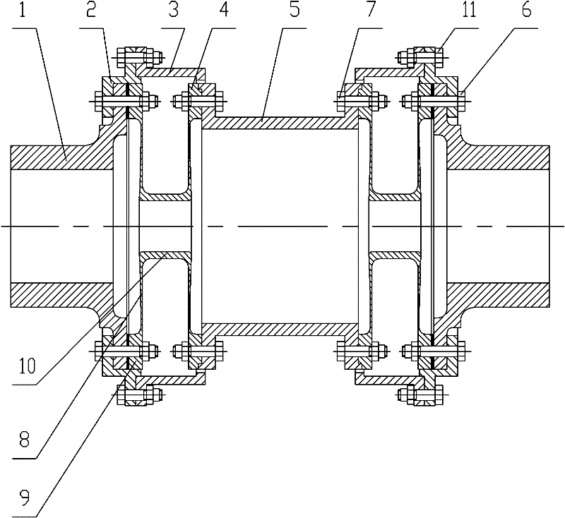
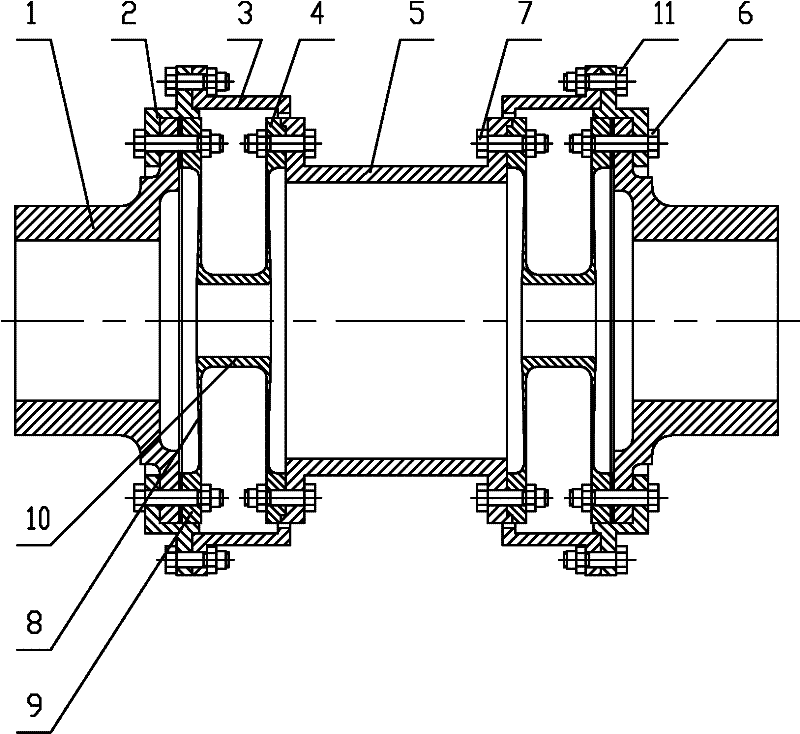
[0015] As shown in the figure: the highly elastic diaphragm coupling structure includes the mounting plate 1, the first guard plate 2, the second guard plate 3, the double diaphragm disc 4, the spacer shaft 5, the first bolt assembly 6, and the second bolt assembly 7. , Diaphragm 8, diaphragm flange 9, diaphragm body 10, third bolt assembly 11, etc.

[0016] The present invention includes a spacer shaft 5, a double diaphragm disk 4 symmetrically installed at both ends of the spacer shaft 6, and a mounting disk 1. The double diaphragm disk 4 has diaphragms 8 on both sides, and the top of the diaphragm 8 is a diaphragm flange 9. The bottoms of the diaphragms 8 on both sides are connected into a whole by the diaphragm body 10, and the double diaphragms 4 are integrally connected to form a U-shaped structure shape. The U-shaped surface of the double diaphragm 4 is deformed to realize t...


PUM


Abstract

The invention relates to a high-elasticity film disk shaft coupling structure which comprises a spacing shaft, double film disks symmetrically arranged at two ends of the spacing shaft and mounting disks. The high-elasticity film disk shaft coupling structure is characterized in that the molded surfaces of the double film disks are curve molded surfaces; the molded surfaces of the double film disks are integrally connected into a U-shaped structure shape; both sides of the double film disks are provided with films, the tops of the films are provided with film disk flanges, and the bottoms of the films at both sides are connected into a whole by film disk bodies; the double film disks are connected with the mounting disks through the film disk flanges at one side and are connected with transmission torque through first bolt assemblies; the film disk flanges at the other sides of the double film disks and the spacing shaft are positioned through convex-concave seam allowances and are connected with the transmission torque through second bolt assemblies; and a first protection plate and a second protection plate cover the exteriors of the double film disks. The high-elasticity film disk shaft coupling structure provided by the invention is of a double-film-disk high-elasticity structure, so that more compensation dosage can be achieved; and the high-elasticity film disk shaft coupling structure provided by the invention is convenient to assemble and disassemble and beneficial to overhaul and maintenance.

Description

technical field [0001] The invention relates to a shaft coupling suitable for a large compensation amount, in particular to a structure of a high-elastic membrane disc shaft coupling. Background technique [0002] For general diaphragm couplings, the axial, angular and radial compensation is mainly realized through the curved surface of a single diaphragm. When the required compensation amount increases, the compensation of a single diaphragm cannot meet the actual needs. . Contents of the invention [0003] The purpose of the present invention is to overcome the deficiencies in the prior art and provide a highly elastic membrane disc coupling structure, which can achieve greater axial, angular and radial compensation by using the high elasticity principle of double membrane discs. [0004] According to the technical solution provided by the present invention, a high-elastic diaphragm coupling structure includes a spacer shaft, double diaphragm discs and mounting discs s...

Claims


Application Information

Patent Timeline
IPC IPC(8): F16D3/72
CPCF16D3/72
Inventor 陶燕频邱宝玉封云
Owner 无锡创明传动工程有限公司
Why Eureka
Try Eureka