
Clutch used for tower crane lifting mechanism

A lifting mechanism and clutch technology, applied in the field of clutches, can solve problems such as short service life, achieve long service life, avoid wear or breakage

Inactive Publication Date: 2012-01-11
李欣
View PDF1 Cites 1 Cited by
  • Summary
  • Abstract
  • Description
  • Claims
  • Application Information

AI Technical Summary

Problems solved by technology

[0004] The purpose of the present invention is to overcome the defects and problems of short service life in the prior art and provide a clutch for tower crane hoisting mechanism with long service life

Method used


Image

  • Clutch used for tower crane lifting mechanism
  • Clutch used for tower crane lifting mechanism
  • Clutch used for tower crane lifting mechanism

Examples


Embodiment Construction

[0013] The present invention will be described in further detail below in conjunction with accompanying drawing and specific embodiment

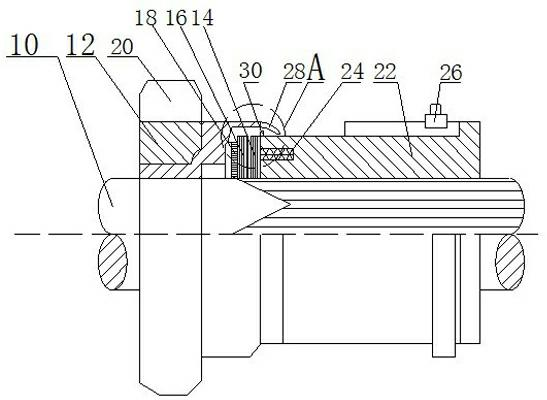
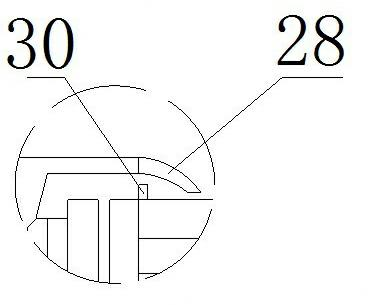
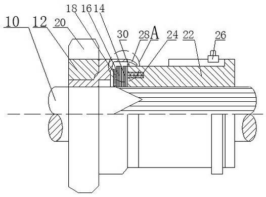
[0014] see figure 1 As shown, a clutch for the hoisting mechanism of a tower crane includes a main shaft 10, a sleeve 12, a driving friction plate 14 and a driven friction plate 16, wherein the sleeve 12, the driven friction plate 16 and the driving friction plate 14 are sequentially set on the On the main shaft 10, an armature 18 is arranged between the driven friction plate 16 and the sleeve 12. The armature 18, the driving friction plate 14 and the driven friction plate 16 are all accommodated in the sleeve 12, and the driven wheel is set on the sleeve 12. 20. An iron core 22 is also set on the main shaft 10, and a coil 24 is arranged in the iron core 22. The active friction plate 14 is in contact with the iron core 22, and a slip ring 26 is arranged on the iron core 22, and a slip ring 26 is arranged on the sleeve 12. One end of the rin...


PUM


Abstract

The invention discloses a clutch used for a tower crane lifting mechanism. The clutch disclosed by the invention comprises a main shaft, a sleeve, a drive friction plate and a driven friction plate, wherein the sleeve, the driven friction plate and the drive friction plate are sequentially sleeved on the main shaft; an armature iron is arranged between the driven friction plate and the sleeve; the armature iron, the drive friction plate and the driven friction plate are accommodated in the sleeve, and a driven wheel is sleeved on the sleeve; an iron core is also sleeved on the main shaft and is internally provided with a coil; and the drive friction plate is contacted with the iron core and a slip ring is arranged on the iron core. The clutch disclosed by the invention is characterized in that one end, adjacent to the slip ring, of the sleeve extends obliquely downwards to form a first protection part; and one end, adjacent to the drive friction plate, of the iron core extends vertically upwards to form a second protection part. The clutch disclosed by the invention has the advantage of longer service life.

Description

technical field [0001] The invention relates to a tower crane hoisting mechanism, in particular to a clutch of the tower crane hoisting mechanism. Background technique [0002] Clutch is a common mechanism in machinery. Its function is mainly to control the output of mechanical power through the clutching and closing of the friction plate. Usually, it can be divided into manual lever type and hydraulic type according to the form of axial force acting on the friction plate. , pneumatic and electromagnetic. The electromagnetic clutch is to use the electromagnetic force to realize the axial engagement and separation of the friction plates. [0003] The Chinese patent authorization announcement number is CN2390049Y, and the invention patent issued on August 2, 2000 discloses an electromagnetic clutch, including a rotor, a coil, an oil-impregnated bearing and an armature. The coil wound on the bobbin is placed in the rotor, The opening at the right end of the rotor is presse...

Claims


Application Information

Patent Timeline
Patent Type & Authority Applications(China)
IPC IPC(8): F16D27/04F16D27/14B66C23/62
Inventor 李欣
Owner 李欣
Learn More