CCD (Charge Coupled Device) suitable for optical fiber gyro reeling machine

A fiber optic gyroscope and winding machine technology, which is used in optical device exploration, TV, color TV components and other directions, can solve problems such as inability to meet precise arrangement requirements, inability to ensure winding quality, and many influencing factors, and achieve convenient cost. and application, facilitate process improvement, observe clearly the effect

Inactive Publication Date: 2012-01-11
BEIHANG UNIV
View PDF3 Cites 8 Cited by
  • Summary
  • Abstract
  • Description
  • Claims
  • Application Information

AI Technical Summary

Problems solved by technology

How to wind high-quality fiber optic rings is very important to the development of fiber optic gyroscopes. Winding rules are the key indicators of high-quality fiber optic rings. However, due to the thinness of optical fibers and many influencing fa

Method used


Image

  • CCD (Charge Coupled Device) suitable for optical fiber gyro reeling machine
  • CCD (Charge Coupled Device) suitable for optical fiber gyro reeling machine
  • CCD (Charge Coupled Device) suitable for optical fiber gyro reeling machine

Examples


Embodiment Construction

[0046] The technical solutions in the present invention will be clearly and completely described below in conjunction with specific embodiments. Apparently, the described embodiments are only some of the embodiments of the present invention, not all of them. Based on the embodiments of the present invention, all other embodiments obtained by persons of ordinary skill in the art without making creative efforts belong to the protection scope of the present invention.

[0047] The embodiments of the present invention are further described in detail below.

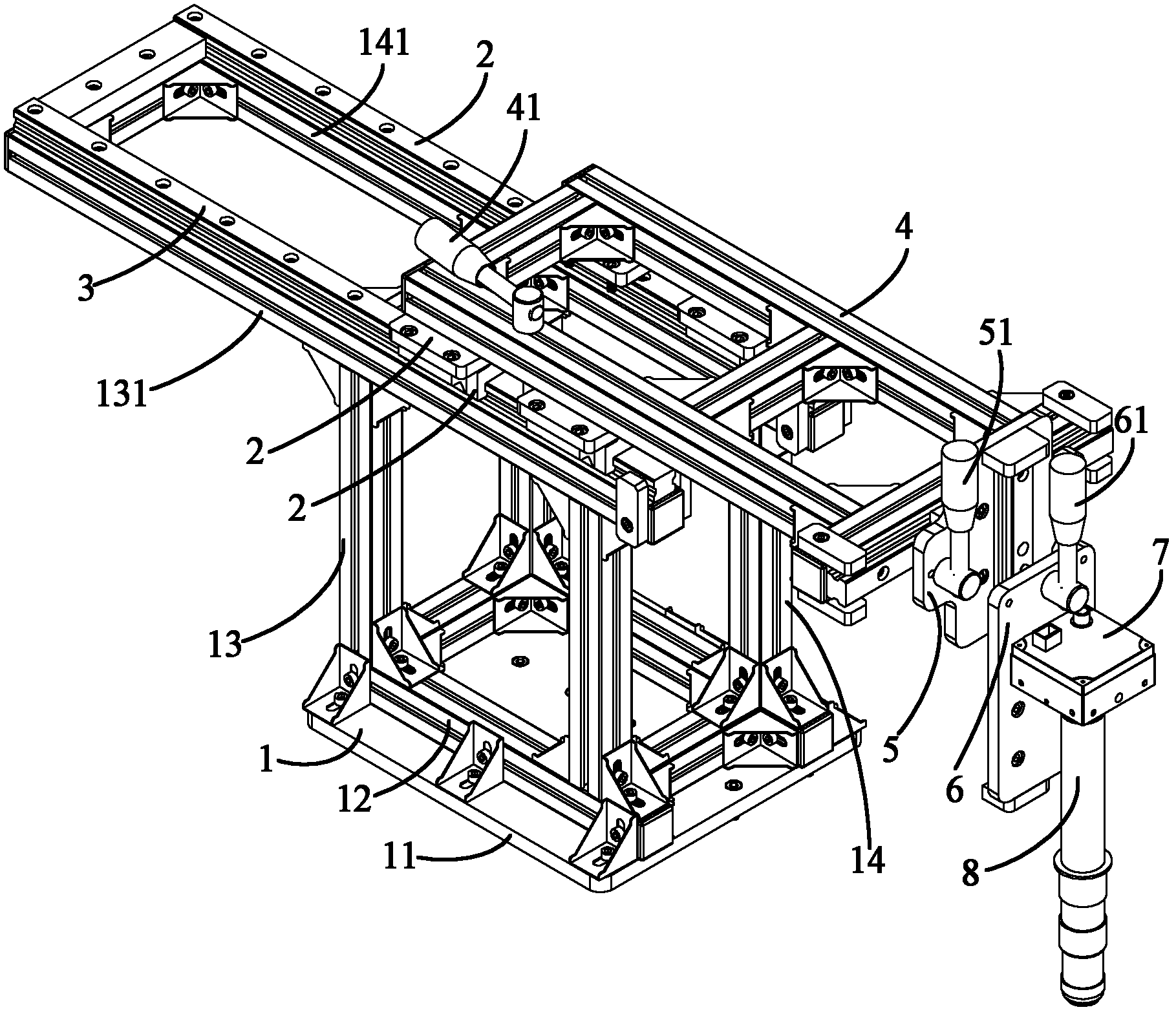
[0048] The embodiment of the present invention provides a CCD device suitable for a fiber optic gyro winding machine, which is a CCD (Charge-coupled Device, charge-coupled device or CCD image sensor) lens used for observation of a fiber optic gyro winding machine devices such as figure 1 As shown, the device includes: a base assembly 1, two horizontal guide rails 2, 3, a sliding beam assembly 4, a slide rail beam assembly 5, ...


PUM


Abstract

The invention discloses a CCD (Charge Coupled Device) suitable for an optical fiber gyro reeling machine, which comprises a base component, two horizontal guide rails, a sliding beam component, a slide rail beam component, a lens holder component, a lens mount and a lens, wherein the base component is in a framework type structure; two beams which are mutually arranged in parallel are horizontally arranged on the base component; the two horizontal guide rails are arranged on the two beams of the base component; the sliding beam component is in a framework type structure and is movably arranged on the two horizontal guide rails; the slide rail beam component is arranged at the front end of the sliding beam component; the slide rail beam component is perpendicular to the two horizontal guide rails in the horizontal direction and can transversely slide at the front end of the sliding beam component; the lens holder component is arranged on the slide rail beam component; the lens mount is arranged on the lens holder component and can vertically slide on the lens holder component; and the lens is arranged on the lens mount. The device disclosed by the invention can freely adjust the position of the lens in the three-dimensional direction, thereby conveniently observing the reeling of the optical fiber gyro reeling machine.

Description

technical field [0001] The invention relates to the field of fiber optic gyro winding machines, in particular to a CCD device suitable for the fiber optic gyro winding machine which can observe the fiber optic gyro winding machine online. Background technique [0002] The fiber optic gyroscope was born in 1976. It is a new type of sensor that uses fiber optic sensing technology to measure the space inertial rotation rate. It has developed into a new mainstream instrument with epoch-making characteristics in the field of inertial technology. Compared with the laser gyroscope, it has higher precision, low cost, small size and light weight. The application prospect of fiber optic gyroscope is very broad. It is not only used in the navigation of aircraft and ships, missile guidance, high-precision position control of spacecraft, but also in the guidance of high-end cars in civilian use, as well as robots and automatic control systems, etc. . [0003] The fiber optic ring is th...

Claims


Application Information

Patent Timeline
IPC IPC(8): G01V8/10H04N5/225H04N5/232
Inventor 董全林张春熹王夏霄潘雄迟悦李慧鹏杨德伟徐宏杰宋凝芳李立京贾明章博刘海霞孟昭魁邵洪峰孟凡念袁水平于成交杨彦杰孙茂多
Owner BEIHANG UNIV
Why Eureka
Try Eureka