Supercharge Your Innovation With Domain-Expert AI Agents!

Hybrid optical cable

A hybrid and optical cable technology, applied in the direction of fiber mechanical structure, etc., can solve the problems of inconspicuous number of optical fibers and limited fiber core density of optical cables, and achieve the effect of small outer diameter of optical cable, stable and reliable optical performance, and large core density

Active Publication Date: 2012-01-11
江苏中伟业通讯设备有限公司
View PDF10 Cites 6 Cited by
  • Summary
  • Abstract
  • Description
  • Claims
  • Application Information

AI Technical Summary

Problems solved by technology

[0003] In the prior art, the Chinese patent number is 200920165319.4, the optical fiber cable named composite optical fiber ribbon and loose fiber, and the utility model patent disclosed optical cable with the announcement number CN 201477244U adopts a combination of ribbon-shaped loose tube and loose-shaped loose tube. To achieve the purpose of increasing the density of optical fibers, the fiber optic cable of this structure is realized by placing loose tubes in the gaps of the ribbon-shaped loose tubes. The number of optical fibers increased in this way is not obvious; the Chinese patent number is 200810174168. It is an optical fiber ribbon optical cable, the invention patent of which the publication number is CN 1013933100A discloses that the optical fiber cable adopts the way that the optical fiber ribbon surrounds the central strength member, and the fiber core density of this optical fiber cable is also limited

Method used


Image

  • Hybrid optical cable
  • Hybrid optical cable
  • Hybrid optical cable

Examples


Embodiment 1

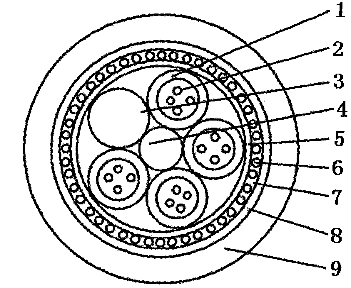
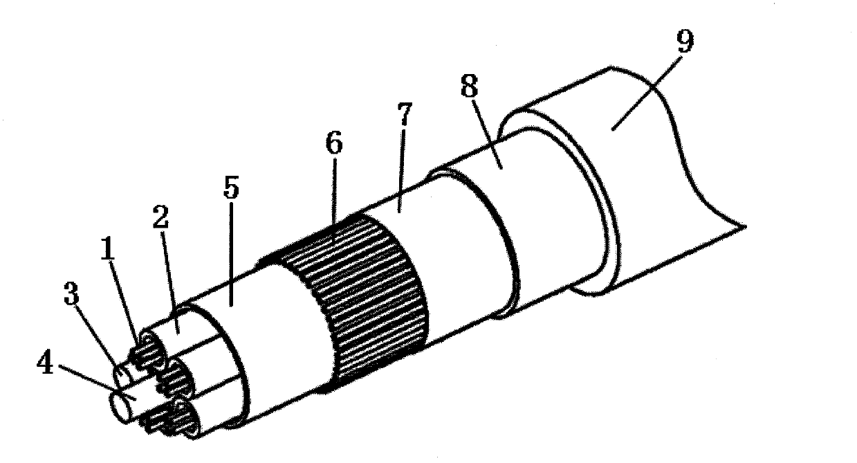
[0031] See figure 1 and figure 2 , a hybrid optical cable, is characterized in that it comprises a center strength member 4 in the center, a plurality of strands twisted around the center strength member SZ or unidirectional helical stranding distribution, and coated on the outside of the strands The isolation layer 5, the optical fiber ribbon 7 longitudinally coated on the isolation layer, the protective layer 8 wrapped on the optical fiber ribbon, and the sheath layer 9 extruded on the protective layer; 4 of the twisted parts are inner A loose tube 1 containing a plurality of optical fibers 2; the twisted part except the loose tube is a solid filling rope 3; the optical fiber ribbon contains a plurality of optical fibers 6 placed parallel to each other; the optical fiber The axis of the fiber is parallel to the axis of the central strength member; the optical fiber ribbons are connected end to end but not connected; the central strength member is steel wire; the material o...

Embodiment 2

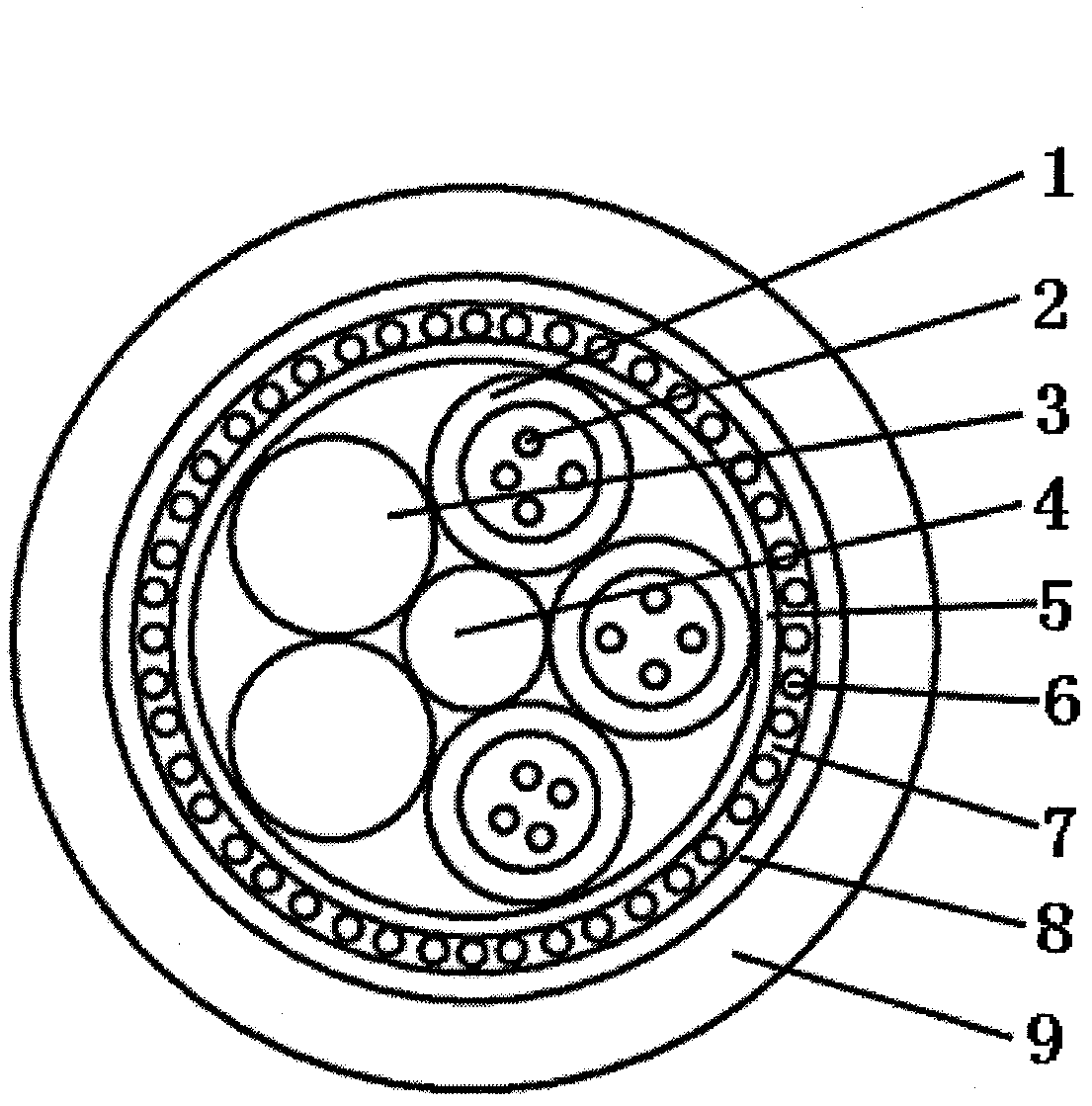
[0033] please see image 3 and refer to figure 2 , a hybrid optical cable, is characterized in that it comprises a center strength member 4 in the center, a plurality of strands twisted around the center strength member SZ or unidirectional helical stranding distribution, and coated on the outside of the strands The isolation layer 5, the optical fiber ribbon 7 longitudinally coated on the isolation layer, the protective layer 8 wrapped on the optical fiber ribbon, and the sheath layer 9 extruded on the protective layer; 3 of the twisted parts are inner A loose tube 1 containing a plurality of optical fibers 2; the twisted parts except the loose tube are two solid filling ropes 3; the optical fiber ribbon contains a plurality of optical fibers 6 placed parallel to each other; the optical fiber The axis of the fiber is parallel to the axis of the central strength member; the optical fiber ribbons are connected end to end but not connected; the central strength member is a gla...

Embodiment 3

[0035] please see Figure 4 and refer to figure 2 and image 3 , a hybrid optical cable, basically the same as the implementation example 2, the difference is that: the three loose tubes are separated by two filling ropes, one is one and the other is two, so that the optical cable The weight is more balanced.

[0036] Of course, the hybrid optical cable described in any of the above implementation examples is characterized in that the optical fiber ribbon can be multiple, the head end of the next optical fiber ribbon is connected to the tail end of the previous optical fiber ribbon, and the last optical fiber ribbon The tail end of the ribbon is connected to the beginning and end of the first optical fiber ribbon.

[0037] Of course, the hybrid optical cable described in any of the above implementation examples is characterized in that the central strength member is a steel wire or a steel strand or a glass fiber reinforced plastic rod.

[0038]Of course, the hybrid optic...


PUM

PropertyMeasurementUnit
Thicknessaaaaaaaaaa
Thicknessaaaaaaaaaa

Abstract

The invention belongs to the technical field of an optical fiber cable and particularly relates to a hybrid type optical cable. The hybrid type optical cable is characterized by comprising a central reinforcing piece in the center, multiple twisting pieces, an isolating layer, optical fiber ribbons, a protective layer and a sheathing layer, wherein the twisting pieces are distributed around the central reinforcing piece in an SZ twisting or unidirectional helical twisting mode; the isolating layer is wrapped outside of the twisting pieces; the optical fiber ribbons are longitudinally wrapped on the isolating layer; the protective layer is wrapped on the optical fiber ribbons; the sheathing layer is extruded and wrapped on the protective layer; at least one of the twisting pieces is a loose sleeve in which multiple optical fibers are arranged; the twisting pieces outside of the loose sleeve are solid filling ropes; multiple light-guide optical fibers which are mutually arranged in parallel are arranged in the optical fiber ribbons; the axis of the light-guide optical fibers is in parallel to the axis of the central reinforcing piece; and the optical fiber ribbons are arranged in anend-to-end mode but not connected. The optical cable provided by the invention has the advantages of large fiber core density, small outer diameter of the optical cable, small material consumption, low cost, simple production equipment and the like, and fiber ribbons and scattered fiber are easy to separate and identify.

Description

technical field [0001] The invention belongs to the technical field of optical fiber and cable, and in particular relates to an optical cable in which loose optical fibers and optical fiber ribbons are combined. Background technique [0002] With the rapid development of the communication industry, especially the development of broadband technology and 3G networks, the demand for optical fibers at home and abroad is increasing day by day. On the other hand, with the rapid development of society, people pay more and more attention to resources. Therefore, people's requirements for low carbon are becoming more and more clear. [0003] In the prior art, the Chinese patent number is 200920165319.4, the optical fiber cable named composite optical fiber ribbon and loose fiber, and the utility model patent disclosed optical cable with the announcement number CN 201477244U adopts a combination of ribbon-shaped loose tube and loose-shaped loose tube. To achieve the purpose of increa...

Claims


Application Information

Patent Timeline
IPC IPC(8): G02B6/44
Inventor 方亚琴蒋菊生
Owner 江苏中伟业通讯设备有限公司
Features
  • R&D
  • Intellectual Property
  • Life Sciences
  • Materials
  • Tech Scout
  • Unparalleled Data Quality
  • Higher Quality Content
  • 60% Fewer Hallucinations
Learn More