
Percussion instrument

一种打击乐器、打击面的技术,应用在打击乐器、乐器、仪器等方向,能够解决打击乐器大型化、设置空间变大、高度方向及左右方向的尺寸变大等问题

Inactive Publication Date: 2012-01-11
ROLAND CORP
View PDF5 Cites 6 Cited by
  • Summary
  • Abstract
  • Description
  • Claims
  • Application Information

AI Technical Summary

Problems solved by technology

[0004] However, in the above-mentioned conventional percussion instruments, the casing 1 is formed in a substantially circular shape in a front view and the drum surface 3 is formed in a circular shape, so the dimensions in the height direction and the left-right direction of the front view become large.
Therefore, there is a problem that the overall size of the percussion instrument increases and the installation space becomes larger.

Method used


Image

  • Percussion instrument
  • Percussion instrument
  • Percussion instrument

Examples


Embodiment Construction

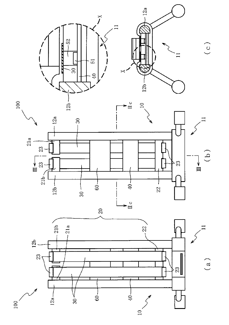
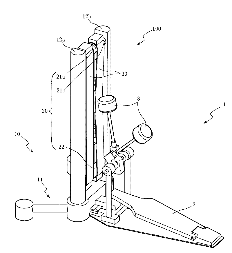
[0026] Hereinafter, preferred embodiments of the present invention will be described with reference to the drawings. First, refer to Figure 1 to Figure 3 , the structure of the electronic percussion instrument 100 of the first embodiment will be described. figure 1It is an external perspective view of the electronic percussion instrument 100 according to the first embodiment of the present invention. figure 2 (a) is a front view of the electronic percussion instrument 100, figure 2 (b) is a rear view of the electronic percussion instrument 100, figure 2 (c) is figure 2 (b) is a cross-sectional view of the electronic percussion instrument 100 along line IIc-IIc. image 3 (a) is figure 2 (b) The sectional view of the electronic percussion instrument 100 of line III-III, image 3 (b) is figure 2 The cross-sectional view of the electronic percussion instrument 100 along line III-III in (b) shows a state when the belt member 30 is struck. In addition, in figure 1 In FIG...


PUM


Abstract

A percussion instrument is configured for minimizing space used for set up for use. In this manner, a belt member 30, which defines the striking surface, is stretched between a first upper stretching member 21a or a second upper stretching member 21b and a lower stretching member 22. Because of the elasticity of the belt member 30, the striking surface of the belt member sinks and rebounds when struck, such that a tension sensation that simulates that of an acoustic percussion instrument is produced. In addition, by forming the belt member 30 in a band shape, the dimension of the striking surface in the width direction can be made small as compared to the case in which the striking surface is configured in a circular shape. Accordingly, the dimensions of the entire electronic percussion instrument 100 can be minimized, such that the space used to set up the electronic percussion instrument 100 can be minimized.

Description

Technical field [0001] The invention involves a percussion instrument, which specializes in percussion instruments that can reduce the space required for setting. Background technique [0002] In the past, Gongzhi had a percussion instrument that imitated acoustic bass drums , For example, in Japan's special Kaiping 11-212566, the following percussion instruments are disclosed: the opening of the cylindrical shell 1, using mesh material composition as the drum 3 of the strike surface, thereby suppressing the drum 3Time strike sounds, and to detect the vibration of drum 3 by blowing sensor 4. [0003] Patent Literature 1: Jobs No. 11-212566, Japan (for example, paragraph [0014], figure 2 wait) [0004] However, in the previous percussion instruments, shell 1 is formed to be roughly circular and the drum surface 3 forms a circular shape, so the size of the height of the face and the size of the left and right directions becomes larger.As a result, there is a problem of large -scale...

Claims


Application Information

Patent Timeline
Patent Type & Authority Applications(China)
IPC IPC(8): G10D13/00
CPCG10D13/024G10D13/006G10D13/029G10D13/26G10D13/02G10D13/11G10D13/03
Inventor 吉野澄
Owner ROLAND CORP
Learn More