
An insulating sleeve for high-voltage cable connectors

A high-voltage cable and connector technology, applied in the electrical field, can solve the problems of short distance, inability to cooperate with transformers, and creepage, etc., so as to increase the surface distance and prevent creepage.

Active Publication Date: 2016-01-20
SHANGHAI RITCHEY ELECTRICAL EQUIP
View PDF5 Cites 0 Cited by
  • Summary
  • Abstract
  • Description
  • Claims
  • Application Information

AI Technical Summary

Problems solved by technology

However, the distance between the three moving contact rods and the connection point of the cable is short, and when the cable connector is used to connect high voltage, creepage will occur between the three moving contact rods and the connection point of the cable, resulting in failure
If the distance between the three moving contact rods is increased, the cable connector will be too bulky and cannot be installed with the transformer

Method used


Image

  • An insulating sleeve for high-voltage cable connectors
  • An insulating sleeve for high-voltage cable connectors
  • An insulating sleeve for high-voltage cable connectors

Examples


Embodiment Construction

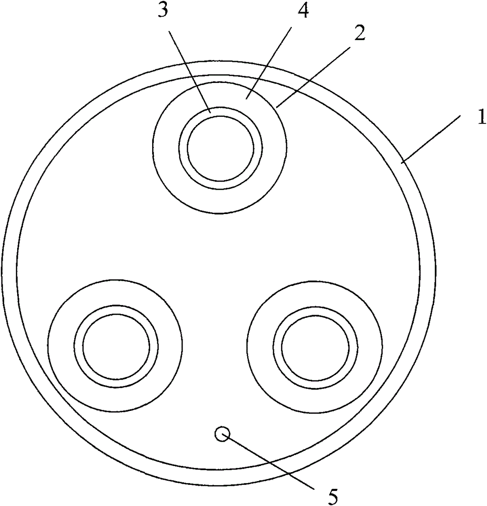
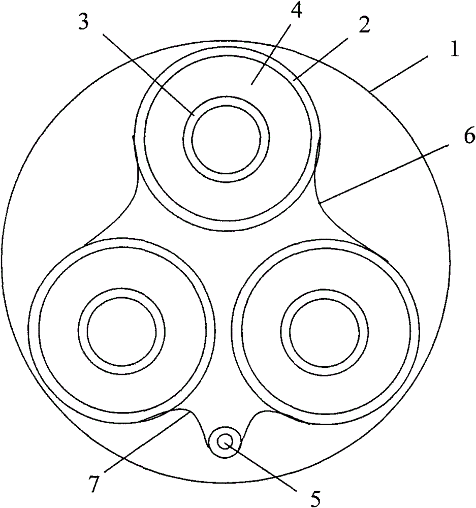
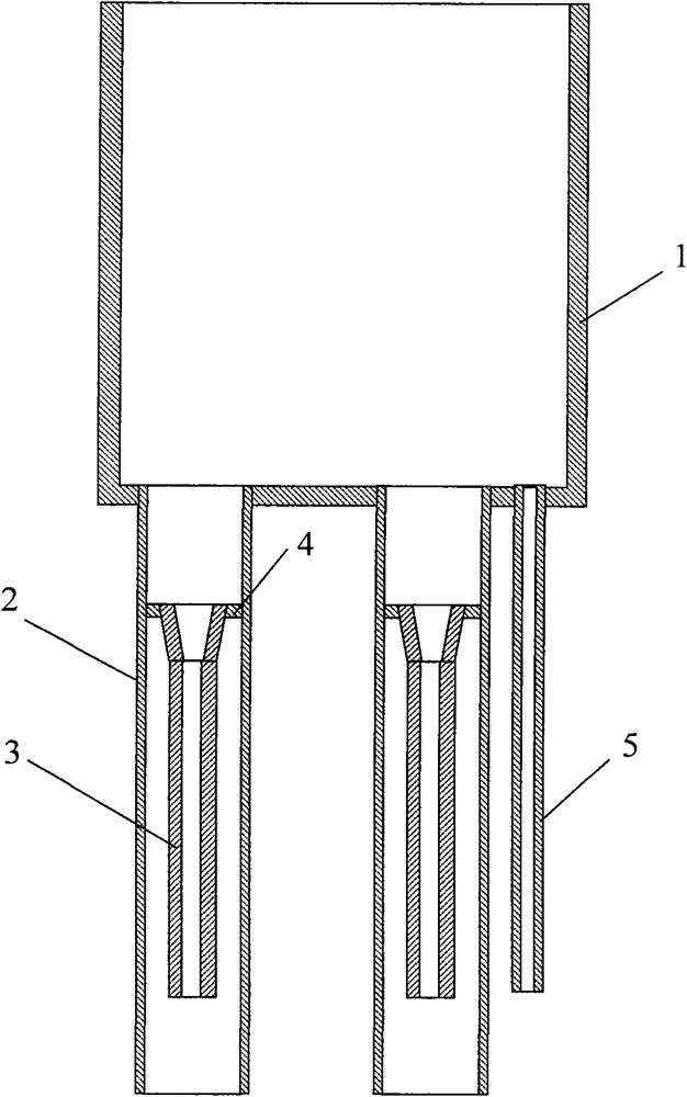
[0016] Such as figure 1 , figure 2 with image 3 As shown, the insulating sleeve used for high-voltage cable connectors of the present invention is composed of an insulating shell 1, wherein the insulating shell 1 is cylindrical, the top surface of the insulating shell 1 is open, and the insulating shell 1 There are three insulating tubes 2 extending downwards from the bottom surface of the housing. The axial direction of any one of the insulating tubes 2 is parallel to the axial direction of the insulating housing 1. Each insulating tube 2 is provided with an insulating inner tube 3. Any one of the insulating inner tubes 3 is coaxial with the insulating tube 2, the length of the insulating inner tube 3 is less than the length of the insulating tube 2, the outer diameter of the insulating inner tube 3 is smaller than the inner diameter of the insulating tube 2, any insulating tube 2 is provided with a radial partition 4 on the inner side of the upper part, the radial partit...


PUM


Abstract

The invention discloses an insulating sleeve for a high-voltage cable connector, comprising an insulating shell. Three insulating tubes are arranged on the bottom surface of the insulating shell in a downward-extending manner and are respectively and internally provided with an insulating inner tube; the outer diameter of the insulating inner tube is less than the inner diameter of the insulating tube; the inner side of the upper part of each insulating tube is provided with a radial partition plate which is arranged below the bottom surface of the insulating shell and a gap is arranged between the radial partition plate and the bottom surface of the insulating shell; the upper end of the insulating inner tube is opened in the radial partition plate, the lower end surface of the insulating inner tube is positioned above the lower end surface of the insulating tube and a gap is arranged between the lower end surface of the insulating inner tube and the lower end surface of the insulating tube. Conducting rods connected with phase lines are placed in the insulating inner tubes; the connecting positions of the upper ends of the conducting rods and a cable are positioned in the insulating tubes and are positioned below the bottom surface of the insulating shell; and the inner wall of the upper end of each insulating tube and the upper side surface of the bottom part of the insulating shell are arranged between the upper ends of the three conducting rods and the cable at intervals, so that the surface distance is greatly increased, and the creepage phenomenon is prevented.

Description

technical field [0001] The invention relates to the electrical field, in particular to a cable connector, in particular to an insulating sleeve for a high-voltage cable connector. Background technique [0002] In the prior art, a cable connector is used to connect the cable and the transformer. Insulating sleeves are used in the cable connector to isolate the moving contact rods on the three phase lines. The applicant proposed the above-mentioned technical solution named the buried transformer high-voltage cable connector in the utility model patent No. CN2755808 published on February 1, 2006. However, the distance between the connection points of the three moving contact rods and the cable is short, and when the cable connector is used to connect high voltage, creepage will occur between the connecting points of the three moving contact rods and the cable, resulting in failure. If the distance between the three moving contact rods is increased, the cable connector will be...

Claims


Application Information

Patent Timeline
Patent Type & Authority Patents(China)
IPC IPC(8): H02G15/18H01B17/58
Inventor 徐兴财
Owner SHANGHAI RITCHEY ELECTRICAL EQUIP
Learn More