Lathe center

A tip and lathe technology, applied in the direction of tailstock/top, turning equipment, toolholder accessories, etc., can solve the problems of small application range of the tip of ordinary lathes, and the ineffective clamping of large inner diameter steel pipes, etc., to achieve easy disassembly and easy realization , Improve production efficiency and product quality

Inactive Publication Date: 2012-01-18
WUXI DAJIN HIGH PRECISION COLD DRAWN STEEL TUBE
View PDF0 Cites 1 Cited by
  • Summary
  • Abstract
  • Description
  • Claims
  • Application Information

AI Technical Summary

Problems solved by technology

[0003] The invention provides a lathe top, which solves the problem that the ordinary lathe top has a small application range and cannot effectively clamp steel pipes with large inner diameters.

Method used


Image

  • Lathe center
  • Lathe center

Examples


Embodiment Construction

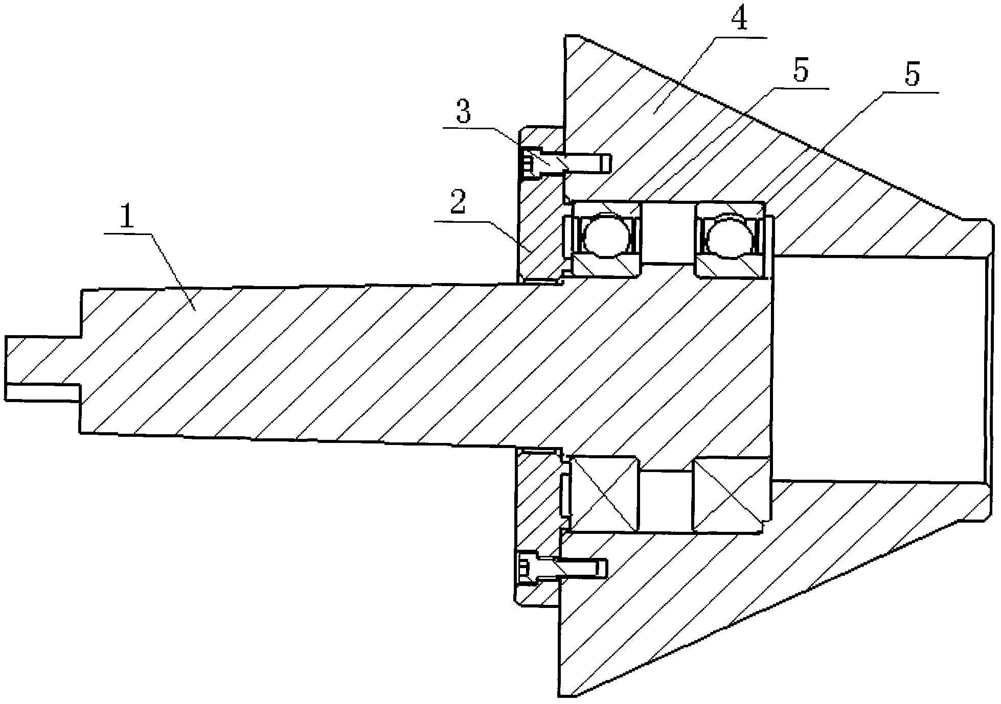
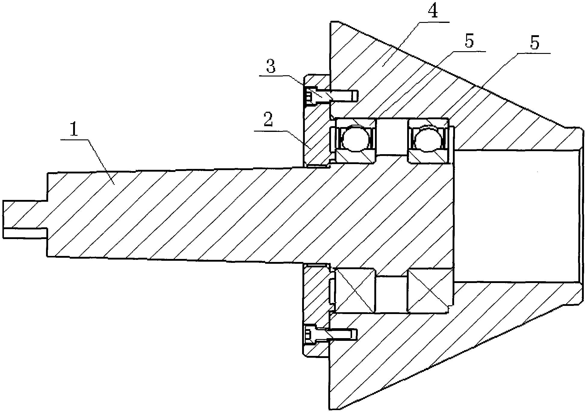
[0013] like figure 1 As shown, a specific embodiment of the present invention is given. In the figure, the plug 4 is a cone with a flat end surface at the top. One end of the assembly shaft 1 is inserted into the stepped hole at the big end of the plug 4, and is installed with the plug 4 through two intervals. The bearing 5 is connected, and the outer side of the bearing 5 is equipped with a gland 2 fixedly installed on the top 4 by screws 3. During processing, the force of the plug 4 is almost all on the inner and outer rings of the bearing 5, avoiding dry friction between the plug 4 and the steel pipe, and greatly extending the service life, and the concentricity of the plug 4 can be guaranteed through the positioning of the outer rings of the two bearings .

[0014] The present invention is easy to install and easy to realize. The common tip of the lathe is replaced by a vertebral head 4 with a flat top, and is connected with the assembly shaft 1 through two bearings 5. F...


PUM


Abstract

The invention discloses a lathe center, which comprises an assembly shaft, a jacking head and a gland, wherein the jacking head is a cone, the top of the jacking head is a flat end face, one end of the assembly shaft is inserted into a step hole at the large end of the jacking head and connected with the jacking head through a bearing, the other end of the assembly shaft is arranged on a lathe, and the gland is arranged at the outer side of the bearing; as a preferably scheme, the jacking head is connected with the assembly shaft through two bearings arranged in interval; and the step hole in the jacking head is a through hole. The lathe center is convenient for installation and easy to realize and has strong generality; and the general center of the lathe is replaced by using the conical jacking head with planar top, the jacking head is connected with the assembly shaft through the two bearings, and the jacking head is matched with a chuck of the lathe, so that effective clamping of steel pipes of multiple specification is realized, and the production efficiency and the product quality are improved.

Description

technical field [0001] The invention relates to lathe accessories, in particular to a lathe top. Background technique [0002] The steel pipe used to produce the oil cylinder needs to be chamfered before welding the flange. When using a common lathe for chamfering, one end of the steel pipe needs to be clamped on the chuck, and the other end should be supported by the top end of the lathe tailstock. The specifications of the steel pipes to be processed range from Φ60-Φ220, while the outer diameter of the top of the tailstock of ordinary lathes is only Φ40 at most, so the top does not reach the inner hole of the steel pipe, which cannot effectively clamp the steel pipe, and the steel pipe is relatively long. Due to the influence of gravity, there will be deflection on the chuck, which will cause jumping and cannot be processed. Contents of the invention [0003] The invention provides a lathe top, which solves the problem that the ordinary lathe top has a small application...

Claims


Application Information

Patent Timeline
Patent Type & Authority Applications(China)
IPC IPC(8): B23B23/00
Inventor 徐彬
Owner WUXI DAJIN HIGH PRECISION COLD DRAWN STEEL TUBE
Why Eureka
Try Eureka