
Precision interference fit assembly method of slender shaft type part

A technology of interference fit and assembly method, applied in metal processing, metal processing equipment, manufacturing tools, etc., can solve the problems of excessive dimensional assembly in the length direction, and the dimensional accuracy of parts assembly cannot be effectively controlled and guaranteed, so as to improve production. Efficiency, ease of implementation, and the effect of eliminating crawling

Inactive Publication Date: 2013-07-10
CHONGQING JIANSHE IND GRP
View PDF5 Cites 0 Cited by
  • Summary
  • Abstract
  • Description
  • Claims
  • Application Information

AI Technical Summary

Problems solved by technology

In this way, the assembly dimensional accuracy of the parts in the length direction cannot be effectively controlled and guaranteed, and the phenomenon of excessive assembly in the length direction often occurs

Method used


Image

  • Precision interference fit assembly method of slender shaft type part
  • Precision interference fit assembly method of slender shaft type part

Examples


specific Embodiment approach 1

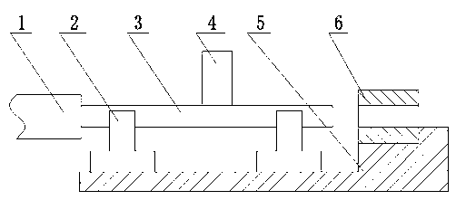
[0017] Specific implementation method 1: An assembly method for precision interference fit of slender shaft parts, using pressure equipment to press-fit directly, pressing the inner sleeve into the outer sleeve, and at the same time In the direction perpendicular to the press-fitting direction, the impact device is used to repeatedly knock on the inner sleeve to make it vibrate until the assembly is completed. During the assembly process, a support device is provided below the inner sleeve, and the support device is relatively fixed to the outer sleeve. The inner sleeve is supported on the support device along the assembly direction. The knocking direction of the impact device is opposite to that of the support device. The pressure The equipment is a hydraulic cylinder, and the impact device is an air hammer.

specific Embodiment approach 2

[0018] Embodiment 2: An assembly method for precision interference fit of slender shaft parts, which divides the assembly into two steps of pre-pressing and fine-pressing from the direction of the assembly length, and the pressure equipment used in pre-pressing is direct pressing The method of press-fitting is carried out, the inner sleeve is pressed into the outer sleeve, and the assembly of most dimensions in the length direction is completed, and then fine-pressing is carried out; during fine-pressing, while maintaining the pressure of the pressure equipment on the inner sleeve, it is in the press-fitting direction In the perpendicular direction, use the impact device to repeatedly knock on the inner sleeve to make it vibrate until the assembly required by the length and size is completed. During the assembly process, a support device is provided below the inner sleeve, and the support device and the outer sleeve are relatively fixedly arranged. The inner sleeve is supported...


PUM


Abstract

The invention discloses a precision interference fit assembly method of a slender shaft type part, and the method is characterized in that a pressure device is used for adopting a direct press-mounting method for press-mounting, an inner sleeve part is pressed into an outer sleeve part, and a percussion device is simultaneously adopted for repeatedly rapping the inner sleeve part to enable the inner sleeve part to shake in the direction which is vertical to the press-mounting direction during a press-mounting process till the assembly is completed. By adopting the method, the creeping phenomenon can be effectively eliminated, the assembly size precision requirement of the slender part in the length direction can be further improved, and the precision size of the slender part in the lengthdirection can be ensured; and through specific experimental verification performed by an applicator, the press-mounting precision in the length direction can be controlled within 0.05mm by adopting the method disclosed by the invention. Simultaneously, the method further has the advantages of being convenient and fast to implement, reducing the labor intensity, improving the production efficiencyand the like.

Description

technical field [0001] The invention relates to an assembly method, in particular to an assembly method requiring precise interference fit for slender parts. Background technique [0002] There are generally two methods for the interference fit assembly of the existing slender parts, one is the direct press-fitting method, and the other is the thermal expansion and contraction method. Among them, the thermal expansion and contraction method has defects such as high assembly cost, inconvenient assembly, and the need to cool the workpiece to affect subsequent processing. At the same time, the effect of thermal expansion and cold contraction to match smaller parts is not obvious. Therefore, the direct press-fitting method is more commonly used. When assembling with the direct press-fitting method, one end of the inner sleeve is opposite to the inner cavity port of the outer sleeve, and then pressure equipment is used to apply pressure from the other end of the inner sleeve alo...

Claims


Application Information

Patent Timeline
Patent Type & Authority Patents(China)
IPC IPC(8): B23P19/027
Inventor 陈小岗任小龙田文松
Owner CHONGQING JIANSHE IND GRP
Learn More