
Dual-shaft synchronous stretching device

A technology of synchronous stretching and stretching frame, which is applied in the field of material stretching devices, can solve the problems of increasing device cost, complex structure, large volume, etc., achieve accurate stretching data and results, simple equipment structure, and avoid complex mechanisms Effect

Active Publication Date: 2012-01-18
萨固密渝锦(重庆)橡塑制品有限公司
View PDF4 Cites 24 Cited by
  • Summary
  • Abstract
  • Description
  • Claims
  • Application Information

AI Technical Summary

Problems solved by technology

However, due to the error of the transmission mechanism in the above structure, it will be difficult to achieve synchronous stretching.
However, for the above structure, to achieve synchronous stretching of the material from the tangential and normal directions, the precision of the transmission mechanism is high, which makes the structure of the whole device more complicated and the volume is larger; Generally, the signal needs to be measured by the detection device (sensing structure) and transmitted to the corresponding control system, and requires a high
Not only increases the complexity of the system, but also greatly increases the cost of the entire device
For general material stretching (including testing or production), it will increase the process cost and the economy is poor

Method used


Image

  • Dual-shaft synchronous stretching device
  • Dual-shaft synchronous stretching device
  • Dual-shaft synchronous stretching device

Examples


Embodiment Construction

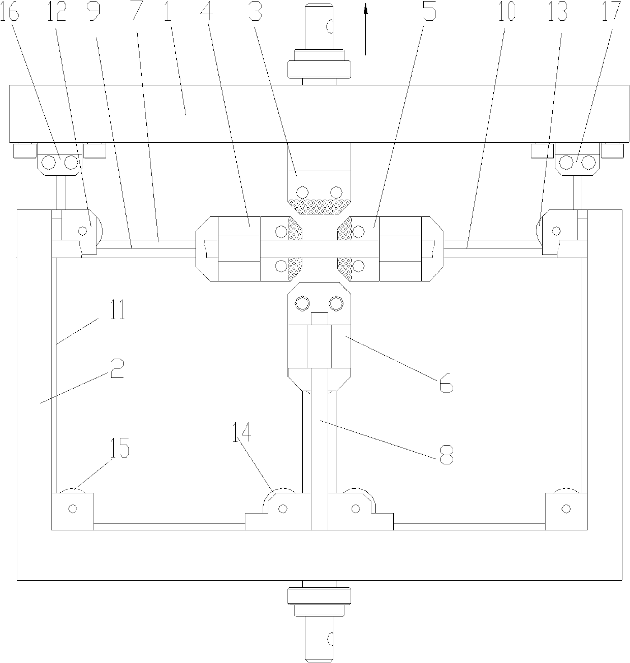
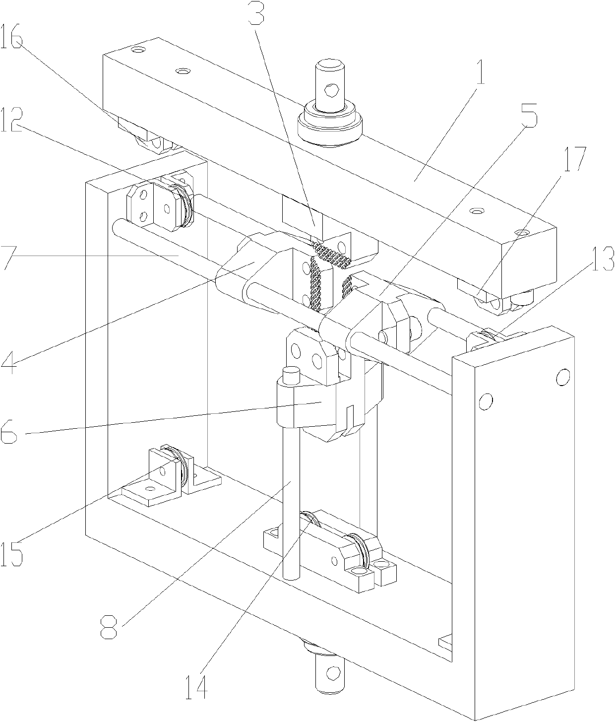
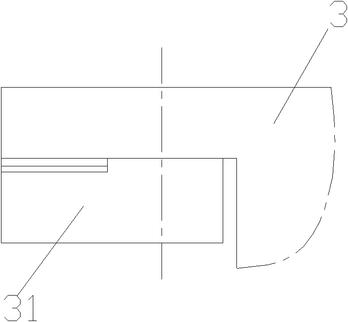
[0022] figure 1 It is a schematic diagram of the structure of the present invention, figure 2 It is a three-dimensional schematic diagram of the structure of the present invention, image 3 It is a schematic diagram of the clamp structure of the present invention, as shown in the figure: the biaxial synchronous stretching device of this embodiment includes a fixed frame 2, a stretching frame 1 and a stretching assembly, and the stretching assembly includes a longitudinal clamp assembly and a transverse clamp assembly , the vertical clamp assembly includes a vertical clamp I3 and a vertical clamp II6 arranged oppositely, and the horizontal clamp assembly includes a horizontal clamp I4 and a horizontal clamp II5 arranged oppositely; the relative setting refers to between the vertical clamp I3 and the vertical clamp II6 and the horizontal clamp I4 It is opposite to the collet used to clamp the workpiece between the horizontal fixture II5 to achieve symmetrical stretching. It be...


PUM


Abstract

The invention discloses a dual-shaft synchronous stretching device, which comprises a fixed frame, a stretching stand and a stretching assembly, wherein a longitudinal clamp I is fixedly arranged on the stretching stand; and a transverse clamp I, a transverse clamp II and a longitudinal clamp II are respectively driven by the stretching stand to realize stretching motion. According to the dual-shaft synchronous stretching device disclosed by the invention, the fixed frame and the stretching stand are combined to form a steering wheel structure; the stretching stand is driven by a stretching and driving device to realize simultaneous stretching motion of dual-shaft four clamps, i.e. the dual-shaft synchronous stretching effect is achieved by uniaxial stretching so as to obtain more accurate stretching data and result; and in addition, the dual-shaft synchronous stretching device has a simple structure, can be used for realizing dual-shaft stretching on a uniaxial stretching tester and solving the problems of complex structure and high cost for bidirectional synchronous stretching in the prior art. The dual-shaft synchronous stretching device has extremely-low cost and is suitable for dual-shaft stretching tests of rubber and other materials.

Description

technical field [0001] The present invention relates to a material stretching device, in particular to a biaxial stretching device for rubber materials, suitable for testing applications and production applications. Background technique [0002] Tensile is the process of elongating the material or sample plane under test or production conditions to obtain the required test parameters and products. Generally, it can be divided into uniaxial, biaxial and multiaxial stretching according to the needs. [0003] Biaxial stretching refers to a construction process that stretches in both the normal and tangential directions. [0004] In the prior art, the biaxial stretching device adopts a combination of clamps along the tangential and normal directions, and uses a relatively independent driving device, or uses the same driving device to drive with different transmission mechanisms, which can realize biaxial stretching . The transmission mechanism mostly adopts a rack and pinion ...

Claims


Application Information

Patent Timeline
IPC IPC(8): B29C55/16
Inventor 周东李红军易舟鑫雷平
Owner 萨固密渝锦(重庆)橡塑制品有限公司
Learn More