Swinging arm type electric lifting wire pay-off device

A pay-off device, swing arm type technology, applied in the field of swing arm type electric lifting pay-off device, can solve the problems of increased weight of the core shaft of the wire reel, difficult operation, difficult clamping of the wire reel 3, etc., and achieves convenient use, structural simple effect

Inactive Publication Date: 2012-01-18
JIANGSU JIACHENG TECH
View PDF4 Cites 14 Cited by
  • Summary
  • Abstract
  • Description
  • Claims
  • Application Information

AI Technical Summary

Problems solved by technology

The above-mentioned pay-off device is only suitable for smaller reels (reels below ?630), when it is necessary to pay off larger reels (reels above ?1250), the center hole of reel 3 is due to the 3 The increase of the diameter increases accordingly, which leads to the thickening of the spool mandrel 1, that is, the weight of the spool mandrel 1 increases, which makes it difficult to clamp the spool 3, and it is difficult for one person to clamp the upper and lower spools 3; In addition, the increase of the wire reel 3 will lead to an increase in the inertia when it is unwound, which will easily lead to the failure of the braking system.

Method used


Image

  • Swinging arm type electric lifting wire pay-off device
  • Swinging arm type electric lifting wire pay-off device
  • Swinging arm type electric lifting wire pay-off device

Examples


Embodiment Construction

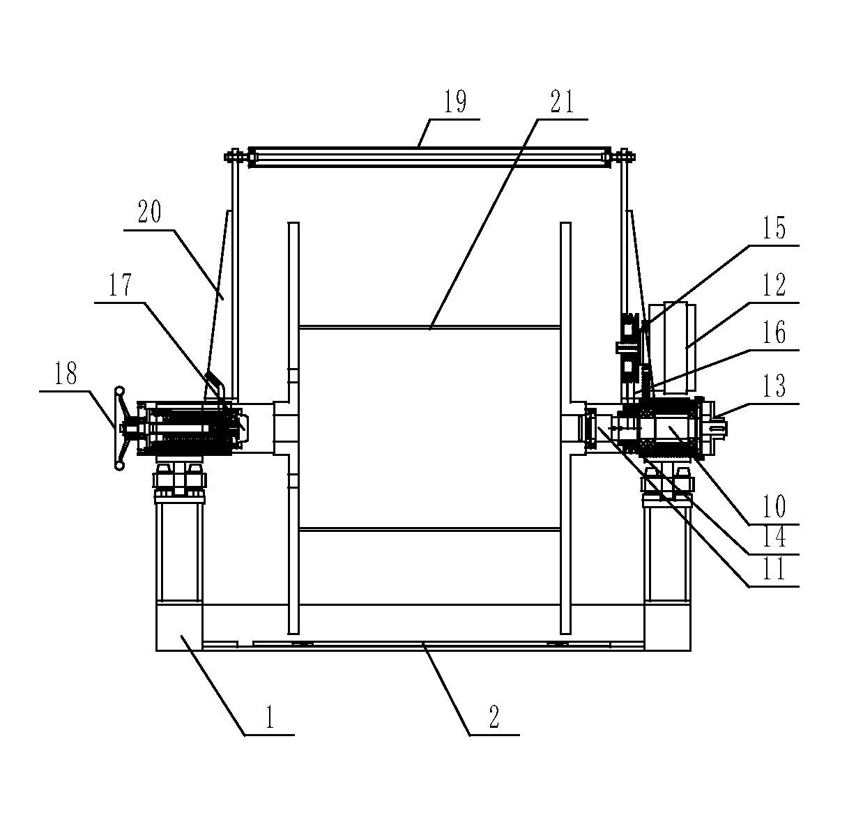
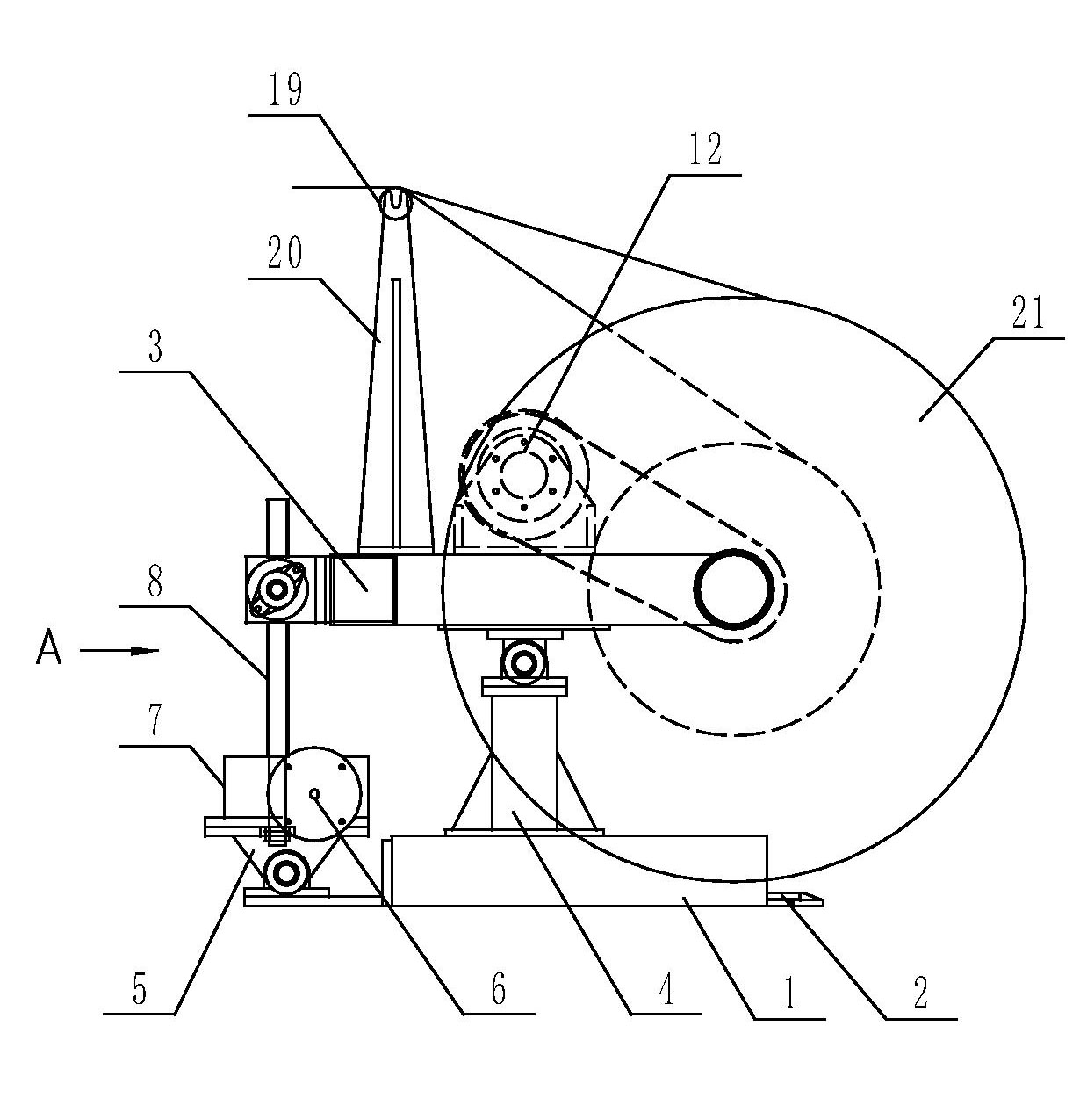
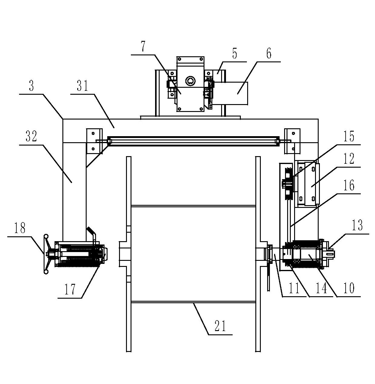
[0017] The swing-arm type electric lifting and pay-off device of the present invention will be further described in detail through specific embodiments below.

[0018] Such as figure 1 , image 3 As shown, the swing arm type electric lifting and unwinding device includes a lower frame 1 at the bottom, a pallet 2 that can move laterally is arranged in the lower frame 1, an upper frame 3 is arranged above the lower frame 1, and an upper frame 3 It is a U-shaped structure connected by a horizontal square tube 31 and two vertical tubes 32. The lower frame 1 is provided with a fulcrum frame 4, the upper end of the fulcrum frame 4 is hinged with the middle part of the upper frame 3, and the upper frame 3 Between the horizontal tube 31 and the lower frame 1, an up and down rotating device is arranged to drive the lifting of the upper frame 3, such as figure 2 , Figure 4 As shown, the described up and down rotation device includes a base 5 hinged with the lower frame 1, the base...


PUM


Abstract

The invention relates to a swinging arm type electric lifting wire pay-off device. The device comprises a lower frame at bottom, wherein a transversely movable supporting plate is arranged in the lower frame, and an upper frame is arranged above the lower frame; the upper frame is a U-shaped structure composed of one transverse square tube and two vertical square tubes which are connected together, and the lower frame is provided with a pivot bracket; the upper end of the pivot bracket is hinged with the middle part of the upper frame, and an up-and-down rotating device for driving the end of the upper frame to lift is arranged between the transverse square tube of the upper frame and the lower frame; one vertical square tube of the upper frame is provided with a main shaft, the front end of the main shaft is provided with a fixed tip cone, the main shaft is connected with a wire pay-off tension device and provided with an electromagnetic brake, and the other vertical square tube of the upper frame is provided with a movable tip cone and a manual rotating disk for driving the movable tip cone to stretch at a corresponding position of the main shaft; a rotary drum is arranged over the upper frame, and the rotary drum is connected with the upper frame through a bracket. The swinging arm type electric lifting wire pay-off device is suitable for paying off the wire for a wire coil.

Description

technical field [0001] The invention relates to a swing arm type electric lifting and unwinding device for unwinding electric wires and cables. Background technique [0002] The currently used pay-off device has a structure such as Figure 5 , Figure 6 , Figure 7 shown. When it works, remove the reel mandrel 1 and the brake disc 2, put the reel mandrel 1 through the center hole of the reel 3, and connect the two ends of the reel 3 with the fixed top cone 4 and the movable top cone 5. Fix it, and then roll the reel 3 up to the top along the inclined wall of the frame 6. At this time, the reel 3 is suspended on the frame 6 through the mandrel 1 of the reel, and then the mandrel 1 of the reel is fixed with the Torx screw 7. Relatively fixed, so that the wire reel 3 can rotate and not slide laterally, thereby realizing the pay-off; in addition, through the pay-off tension formed between the belt 8 and the brake disc 2, the control of the pay-off speed is realized. The abov...

Claims


Application Information

Patent Timeline
Patent Type & Authority Applications(China)
IPC IPC(8): B65H54/553B65H54/70
Inventor 钱国平王广勤刘慧慧
Owner JIANGSU JIACHENG TECH
Why Eureka
Try Eureka