Suspension apparatus of ship main engine

A technology for a suspension device and a ship's main engine, which is applied in the directions of transportation and packaging, load hanging components, etc., can solve the problems of large overall force of the hanging beam, troublesome production, complex structure, etc. Low, guaranteed safety effect

Inactive Publication Date: 2012-01-18
ZHEJIANG ZHENGHE SHIPBUILDING
View PDF9 Cites 4 Cited by
  • Summary
  • Abstract
  • Description
  • Claims
  • Application Information

AI Technical Summary

Problems solved by technology

However, when the hanging beam is hoisted, the overall force of the hanging beam is large, and the structure is complicated, and the cooperation of multiple pairs of pulley blocks is required, which is not only troublesome to manufacture, but also high in cost, so its structure still needs to be improved.

Method used


Image

  • Suspension apparatus of ship main engine
  • Suspension apparatus of ship main engine
  • Suspension apparatus of ship main engine

Examples


Embodiment 1

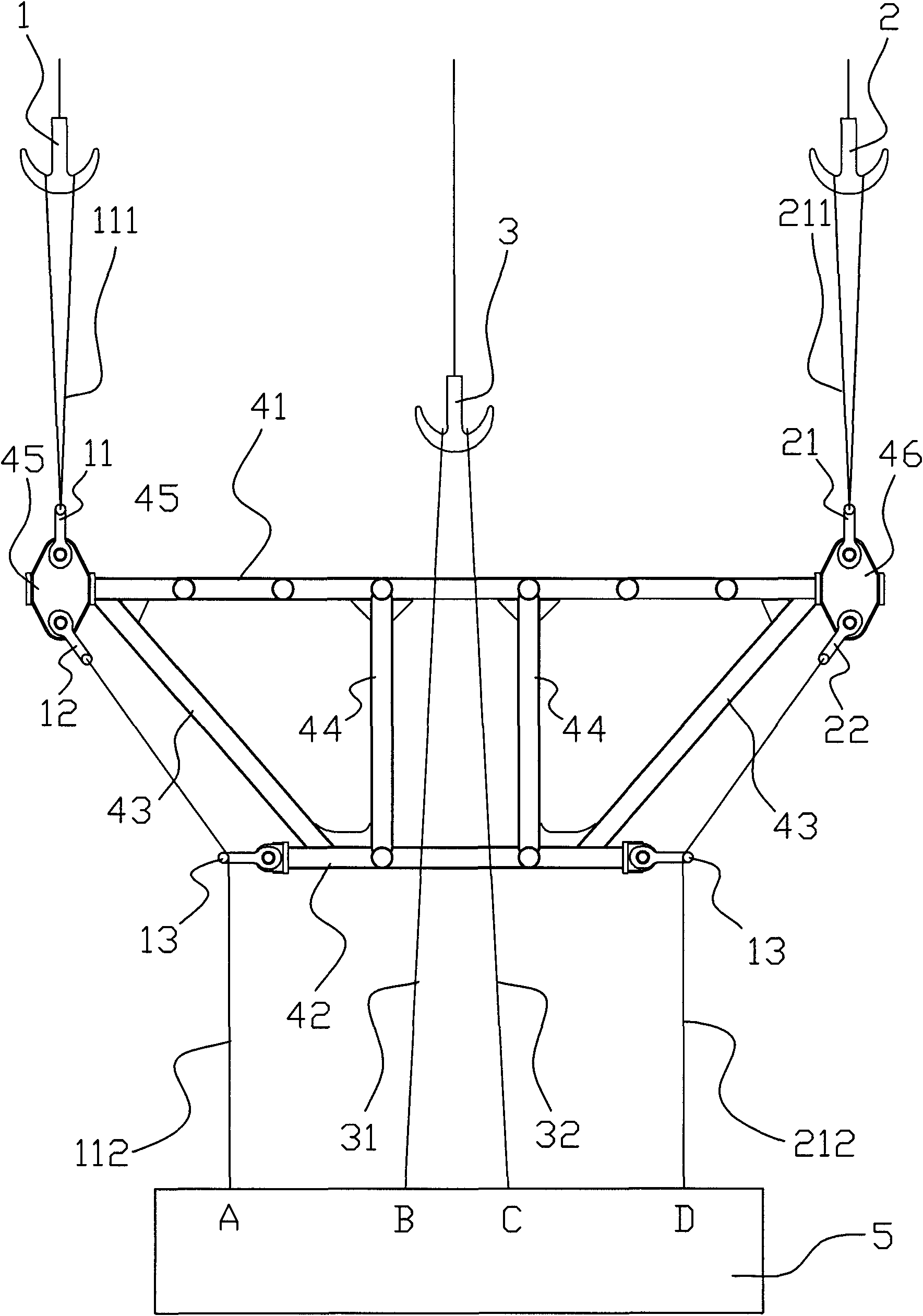
[0019] Embodiment 1. The suspension device of the main engine of the ship in this embodiment includes a wire rope and a hanger. Steel rope comprises first steel rope 111, the second steel rope 211, the 3rd steel rope 112, the 4th steel rope 212 and middle part steel rope, the top left end of described hanger is connected with the first traction part by first steel rope 111, the The right end of the top is connected with the second traction part through the second wire rope 211, the bottom left end of the hanger is extended to the first lifting point A of the main engine 5 through the third wire rope 112, and the bottom right end of the hanger is passed through the fourth wire rope 212 Extending to the fourth hanging point D of the main engine 5, the middle part of the hanger is provided with a space for the middle steel wire rope to extend from top to bottom through the middle of the hanger to the corresponding second hanging point B and third hanging point C, so The upper end...

Embodiment 2

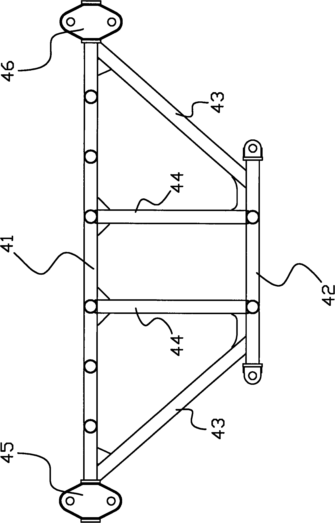
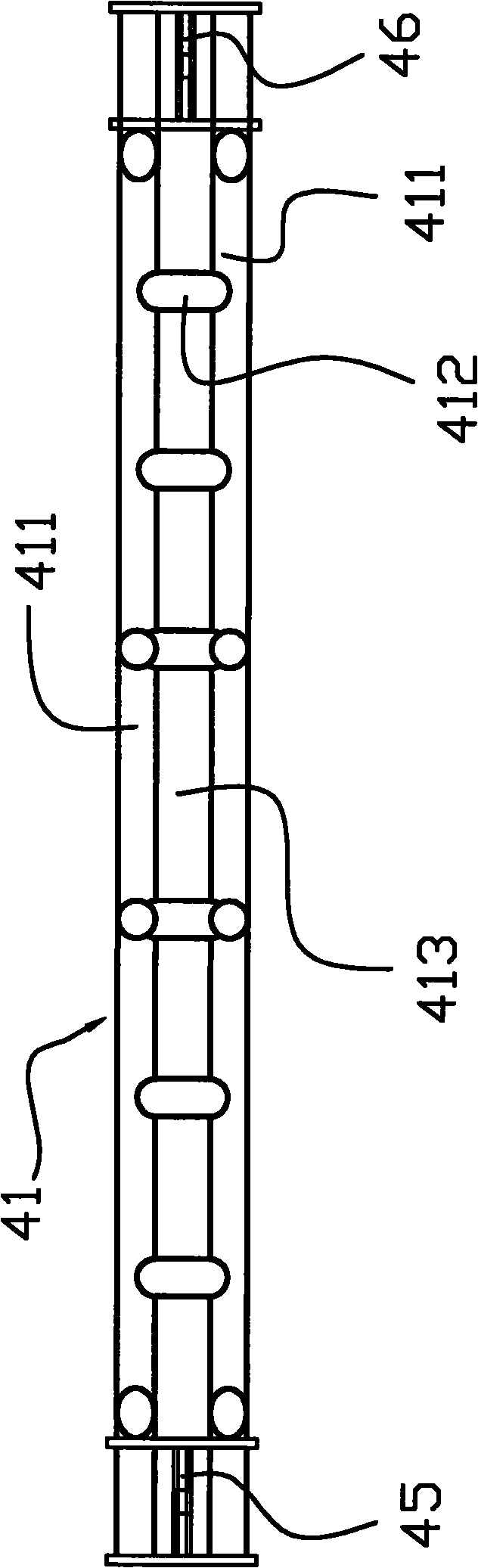
[0021] Embodiment two, such as Figures 1 to 4 As shown, the hanger in this embodiment includes an upper beam 41 and a lower beam 42, and the upper beam 41 and the lower beam 42 are connected by connecting rods. The hanger is wide with the upper beam 41 and narrow with the lower beam 42 trapezoidal, the lower end of the first steel wire rope 111 is connected to the left end of the upper beam 41, the lower end of the second steel wire rope 211 is connected to the right end of the upper beam 41, and the upper end of the third steel wire rope 112 passes through the left end of the lower beam 42 The movable lug 13 of the upper beam 41 is connected to the left end, and the upper end of the fourth wire rope 212 passes through the movable lug 13 at the right end of the lower beam 42 and is connected to the upper beam 41 right end. The left end of the upper beam 41 is provided with a left hanging plate 45, and the first hanging lug 11 is detachably arranged on the top of the left hang...


PUM


Abstract

The invention relates to a suspension apparatus of a ship main engine. The suspension apparatus comprises wire ropes, and further comprises a suspension frame. A left end on the top of the suspension frame is connected with a first traction part through a first wire rope (111). A right end on the top of the suspension frame is connected with a second traction part through a second wire rope (211). A left end on the bottom of the suspension frame extends to a first suspension point (A) of a main engine (5) through a third wire rope (112). A right end on the bottom of the suspension frame extends to a fourth suspension point (D) of the main engine (5) through a fourth wire rope (212). A middle portion of the suspension frame is provided with space, wherein a middle wire rope passes through the middle portion of the suspension frame from top to bottom, and extends to a corresponding second suspension point (B) and a corresponding third suspension point (C) in the space. An upper end of the middle wire rope is connected with a third traction part. Compared to the prior art, the apparatus provided by the present invention has the following advantages that: the structure of the apparatus is simple; the pulley block is not required; the apparatus is easy to be used; the production cost of the apparatus is low; the suspension beam structure of the apparatus is solid and stable so as to provide longer service life.

Description

technical field [0001] The invention relates to the technical field of a lifting device, in particular to a suspension device for a main engine of a ship. Background technique [0002] There is a Chinese utility model patent with the patent number 201020000967.7 titled "Multi-functional upper trolley suspension beam of shipbuilding gantry crane" which discloses a multifunctional upper trolley suspension beam of shipbuilding gantry crane, which includes a crossbeam, and is characterized in that: on the crossbeam There are several pin shaft seats fixed, and a movable pulley mechanism is respectively hinged on two of the pin shaft seats. The upper end of the rod passes through the middle hole of the hook beam and is screwed together with the hook nut in the connecting arm. A thrust bearing is set between the boom and the hook beam, and a movable pulley is arranged at the lower end of the boom. There is an intermediate pulley mechanism in the middle of the beam, which includes ...

Claims


Application Information

Patent Timeline
Patent Type & Authority Applications(China)
IPC IPC(8): B66C1/12
Inventor 熊贤早辛登恒
Owner ZHEJIANG ZHENGHE SHIPBUILDING
Why Eureka
Try Eureka