Circuit for detecting locked point current of micro motor

A technology of current detection circuit and micro motor, which is applied in the electronic field to achieve the effect of improving reliability, reducing system power consumption and avoiding burnout

Inactive Publication Date: 2012-01-18
SUPEC SUZHOU
View PDF8 Cites 25 Cited by
  • Summary
  • Abstract
  • Description
  • Claims
  • Application Information

AI Technical Summary

Problems solved by technology

If the locked rotor current is set under the minimum 1.2V condition, it will act before the locked rotor occurs at 2.8V; on the contrary, if it is set according to the highest voltage condition, it cannot be judged even if the locked rotor occurs under the 1.2V condition.

Method used


Image

  • Circuit for detecting locked point current of micro motor
  • Circuit for detecting locked point current of micro motor
  • Circuit for detecting locked point current of micro motor

Examples


Embodiment Construction

[0040] The embodiment of the present invention provides a micro-motor stall point current detection circuit, which is used to correctly detect the stall point current when the value of the micro-motor working power changes, so as to prevent the micro-motor from being burned due to over-current due to stalling.

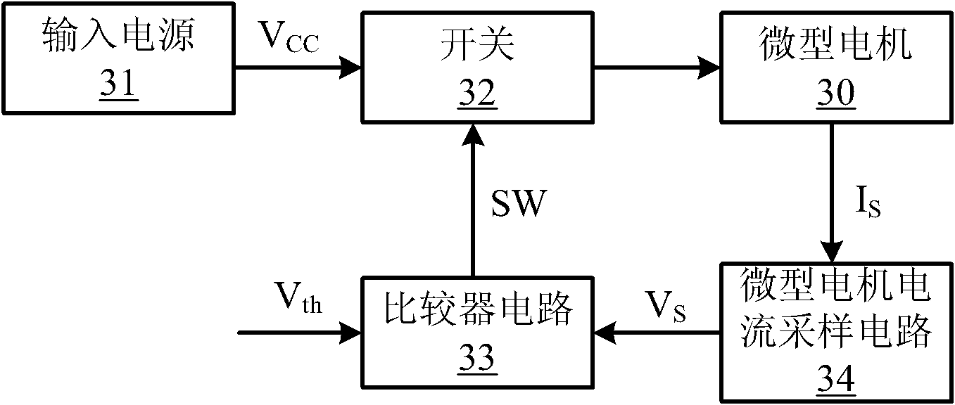
[0041] refer to figure 2 , which is a schematic block diagram of a micro-motor stall point current detection circuit according to Embodiment 1 of the present invention, including:

[0042] The input power supply 31, the voltage value of the input power supply is variable, and is used to provide the working voltage V for the micro motor 30 CC ;

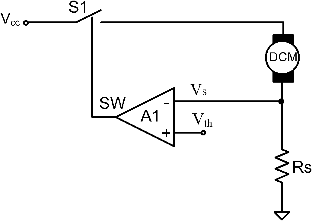
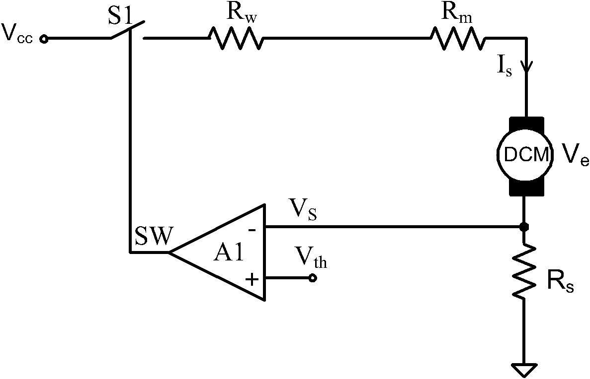
[0043] The micro-motor current sampling circuit 34 is used to sample the current of the micro-motor 30 to generate a sampling voltage V S ;

[0044]A switch 32, one end of the switch 32 is connected to the input power supply 31, and the other end is connected to the micro motor 30, for controlling the working state of the m...


PUM


Abstract

The embodiment of the invention discloses a circuit for detecting a locked point current of a micro motor, which is used for accurately detecting the locked point current of the micro motor. The circuit for detecting the locked point current of the micro motor, disclosed by the embodiment of the invention, comprises the micro motor, an input power supply, a micro motor current sampling circuit, a switch and a comparer circuit, wherein the voltage value of the input power supply is variable, the input power supply is used for providing a working voltage to the micro motor; the micro motor current sampling circuit is used for sampling the current of the micro motor and generating a sampling voltage; one end of the switch is connected with the input power supply, the other end of the switch is connected with the micro motor, the switch is used for controlling the working state of the micro motor; one input end of the comparer circuit receives the sampling voltage, the other input end of the comparer circuit receives a reference voltage, the reference voltage and the input power supply are in a direct proportion relation, the comparison output end of a comparer outputs a switching signal used for controlling switching on and off of a drive switch.

Description

technical field [0001] The invention relates to the field of electronic technology, in particular to a current detection circuit for a locked-rotor point of a micro-motor. Background technique [0002] In the drive of micro motors for instruments and meters, it is generally judged whether the motor is blocked by detecting the magnitude of the current flowing through the micro motor. The schematic diagram of the micro motor stall current detection circuit is as follows: Figure 1A shown, the input supply V CC Input one end of the controlled switch S1, the other end of the controlled switch S1 is connected to the micro motor, the micro motor and the measuring resistance R S series, that is, by measuring the resistor voltage V S Characterize the current I flowing through the micromotor S , comparator A1-input extracts the measured resistance voltage V S , the other input terminal is connected to the reference voltage V th , the output terminal of the comparator controls th...

Claims


Application Information

Patent Timeline
Patent Type & Authority Applications(China)
IPC IPC(8): G01R31/34G01R19/165
Inventor 范立新
Owner SUPEC SUZHOU
Why Eureka
Try Eureka