Multi-magnetic circuit disk type motor

A disc motor and multi-magnetic circuit technology, which is applied to the magnetic circuit rotating parts, magnetic circuit shape/style/structure, electrical components, etc., can solve the problem of large magnetic loss, complicated manufacturing process, and problems of multi-disk permanent magnet synchronous motor Low efficiency and other problems, to achieve the effect of light weight, small volume, simple and compact structure

Inactive Publication Date: 2012-01-18
WUHAN ZHENXING TIANDI ELECTROMECHANICAL
View PDF9 Cites 18 Cited by
  • Summary
  • Abstract
  • Description
  • Claims
  • Application Information

AI Technical Summary

Problems solved by technology

The multi-disk permanent magnet synchronous motor takes into account the double-sided magnetism of the rotor and the combination of multiple disc motors. However, in the multi-disk permanent magnet synchronous motor, the stator is made of silicon steel sheets and their slots. Composed of winding coils, the magnetic loss is relatively large, and each set of motors still uses the fact that each stator disk is affected by the single-sided magnetism of a rotor. Therefore, the multi-disk permanent magnet synchronous motor has large magnetic loss, The production process is complicated, the volume is large, and the efficiency is not high

Method used


Image

  • Multi-magnetic circuit disk type motor
  • Multi-magnetic circuit disk type motor
  • Multi-magnetic circuit disk type motor

Examples


Embodiment Construction

[0028] Preferred embodiments of the present invention will be further described below in conjunction with the accompanying drawings.

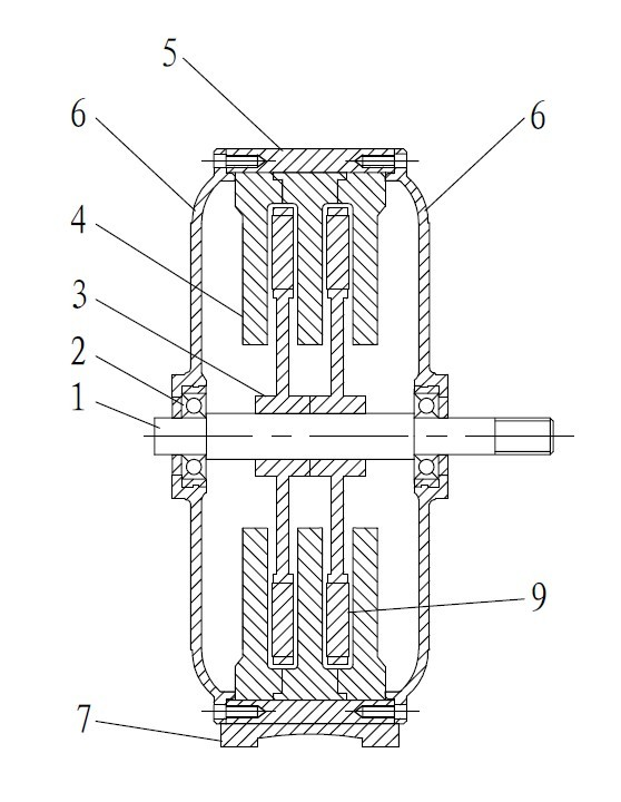
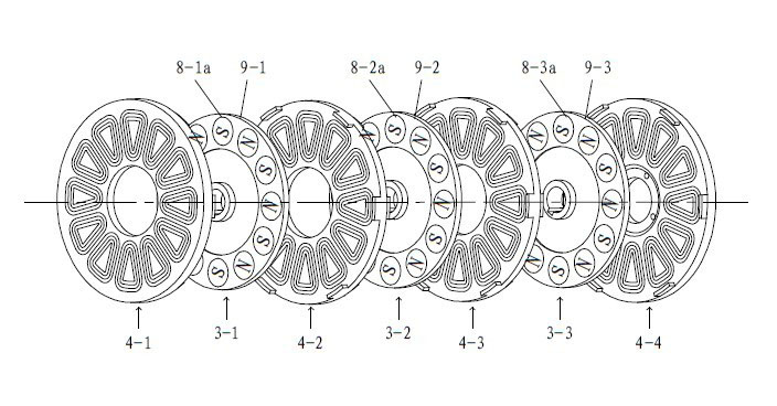
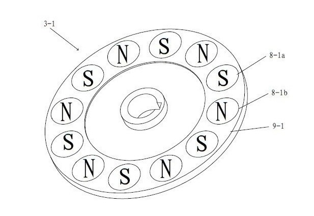
[0029] figure 1 with figure 2 A multi-magnetic disc motor of the present invention is shown. The multi-magnetic circuit disc motor of the present invention includes: a housing 5, a base 7, an end cover 6, a rotor main shaft 1, a bearing 2, a plurality of rotors 3, and a plurality of stator windings 4; the housing 5 is connected and fixed to the base 7, and the end cover 6 It is connected and fixed with the casing 5, a plurality of stator windings 4 are connected and fixed with the end cover 6, the rotor main shaft 1 and the end cover 6 are assembled through the bearing 2, and the rotor 3 and the rotor main shaft 1 are connected and fixed. Each component can be connected and fixed in a traditional way, such as bolts and the like. Its input and output parts can respectively be connected with existing power sources and existing work devices, s...


PUM


Abstract

The invention relates to a multi-magnetic circuit disk type motor, which comprises end covers (6), a rotor main shaft (1), m-1 rotors (3) and m stator windings (4), wherein m is a positive integer more than 2. The m-1 rotors (3) are all fixedly connected with the rotor main shaft (1) and arranged at intervals with the stator windings. The outmost two stator windings are fixedly connected with adjacent end covers. The rotor comprises a rotor disk and a plurality of magnetic steels, wherein each magnetic steel runs through the rotor disk, so that two magnetic poles of each magnetic steel are exposed on the two sides of the rotor disk respectively; and the magnetic steels are arranged on the same side of the rotor disk in a way that the magnetic poles are alternate. The stator winding comprises a winding disk and a coil array. Due to the adoption of a design in which the stator winding acts on the rotors on the two sides of the stator winding, the number of the stator windings is decreased; moreover, the stator winding of the multi-magnetic circuit disk type motor does not adopt a structure in which coils are wound by silicon steel sheets, so production cost is further decreased.

Description

[0001] technical field [0002] The present invention relates to a disc motor, and more particularly to a multi-magnetic circuit disc motor. [0003] Background technique [0004] With the development of electric motors, people realized that ordinary cylindrical motors have problems such as low iron core utilization, while disc motors have been recognized by the market and widely used for their high efficiency, light weight, and stable operation. [0005] The Chinese invention patent application with the application number 201010000675.8 discloses an axial magnetic field disc motor, which winds metal wires tightly and neatly to form independent coils, and multiple independent coils are interlocked and arranged in a circular axis along the circular axis. For the electromagnetic array, the circular electromagnetic array is integrally molded with a resin material added with heat conductors to form an electromagnetic array ring embedded with independent coils, and the electrom...

Claims


Application Information

Patent Timeline
Patent Type & Authority Applications(China)
IPC IPC(8): H02K16/00H02K1/27H02K3/04
Inventor 钟先成阳元发袁誉斌欧阳明
Owner WUHAN ZHENXING TIANDI ELECTROMECHANICAL
Why Eureka
Try Eureka