
Online flusher

A flusher and flushing pipe technology, applied in the field of flushers, can solve the problems of high silicon wafer fragmentation rate, heavy line marks, decline in economic value, etc., and achieve the effect of improving economic benefits and avoiding position movement

Inactive Publication Date: 2012-01-25
ZHENJIANG DACHENG NEW ENERGY
View PDF4 Cites 2 Cited by
  • Summary
  • Abstract
  • Description
  • Claims
  • Application Information

AI Technical Summary

Problems solved by technology

At this time, if the tail is larger than 100mm, the remaining part must be re-machined and reused. However, since the silicon rod has been removed and degummed before, the cut silicon wafer is taken out, and the rod is reinstalled to make the position of the silicon rod shift. As a result, the fragmentation rate of silicon wafers is high, usually exceeding 30%, and all the cut silicon wafers are heavy line marks, and the economic value drops a lot

Method used


Image

  • Online flusher
  • Online flusher
  • Online flusher

Examples


Embodiment Construction

[0009] Below in conjunction with accompanying drawing and specific embodiment, further illustrate the present invention, should be understood that these embodiments are only for illustrating the present invention and are not intended to limit the scope of the present invention, after having read the present invention, those skilled in the art will understand various aspects of the present invention Modifications in equivalent forms all fall within the scope defined by the appended claims of this application.

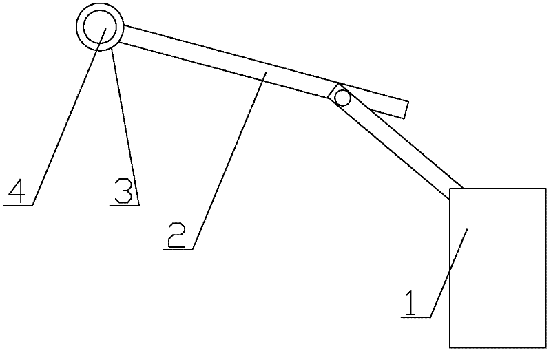
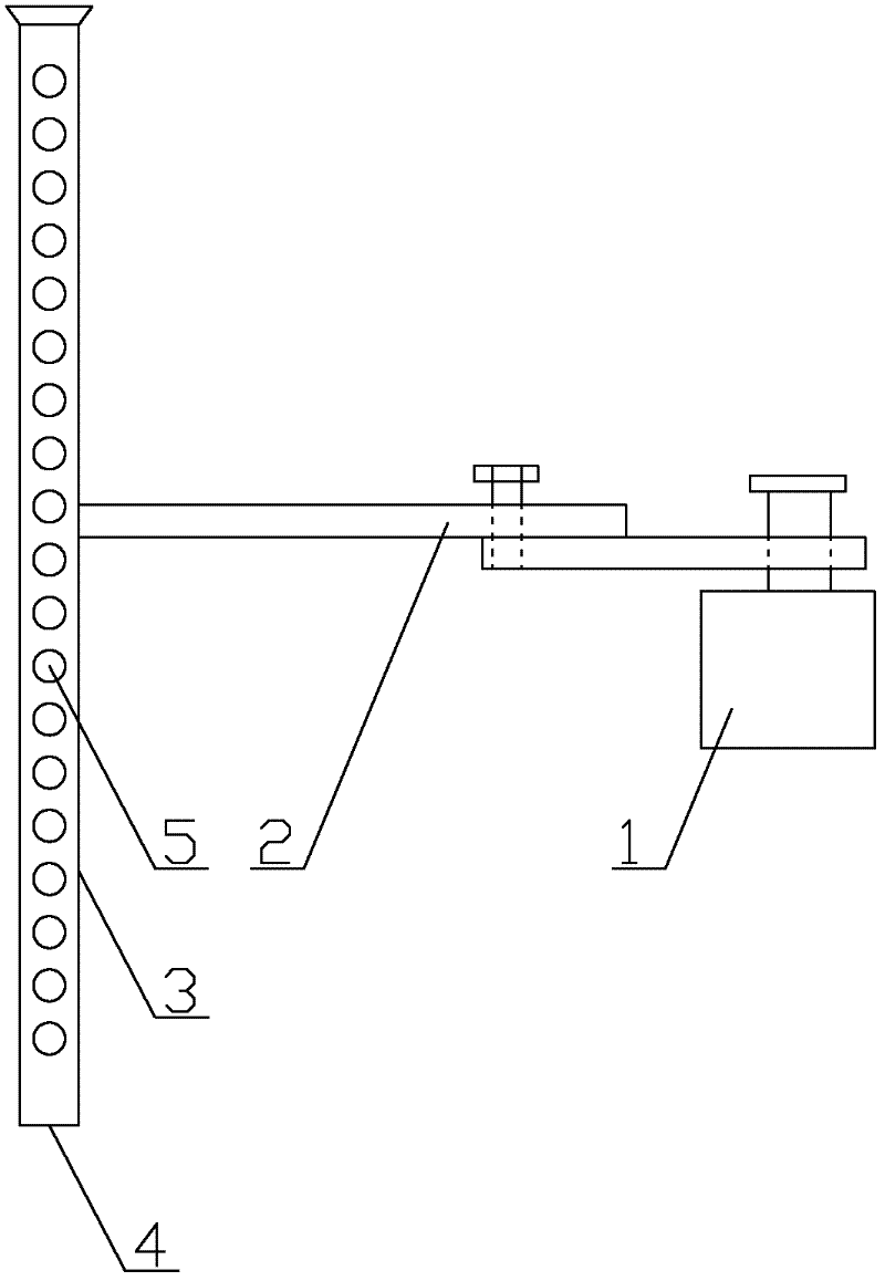
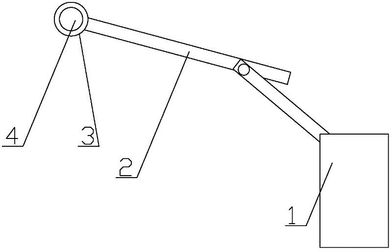
[0010] as attached figure 1 , 2 As shown, an online washer includes a fixed seat 1, a connecting rod 2 and a flushing pipe 3, one end of the connecting rod 2 is connected with the fixed seat 1, and the other end is connected with the flushing pipe 3; one end of the flushing pipe 3 is a water inlet 4, and the other One end is blocked, and a water spray hole 5 is arranged on the flushing pipe 3 .

[0011] When the present invention is in use, the entire washer is fixed o...


PUM


Abstract

The invention discloses an online flusher which comprises a fixed base, a connecting rod and a flushing pipe, wherein one end of the connecting rod is connected with the fixed base, and the other end of the connecting rod is connected with the flushing pipe; and a water inlet is formed at one end of the flushing pipe. The online flusher has the advantages that a silicon wafer on the front part of a machined silicon rod on a cutter is flushed directly by the online flusher, so that the silicon piece is degummed and pulled out to prevent the movement of positions caused by the reinstallation of the disassembled and degummed silicon rod, the fragment rate of the silicon wafer is reduced to about 5 percent, and the economic benefit is improved.

Description

technical field [0001] The invention relates to a flushing device, in particular to a device for flushing devices or components in an online working state. Background technique [0002] In the production process of the solar photovoltaic industry, when the silicon rod is processed by a multi-wire cutting machine, the wire breakage often occurs in the middle of the silicon rod. Now most manufacturers use the method of reconnecting the broken wire and cutting the silicon rod. The front part continues to be processed and the tail is abandoned. At this time, if the tail is larger than 100mm, the remaining part must be re-machined and reused. However, since the silicon rod has been removed and degummed before, the cut silicon wafer is taken out, and the rod is reinstalled to make the position of the silicon rod shift. As a result, the fragmentation rate of silicon wafers is high, usually more than 30%, and all the cut silicon wafers are heavy line marks, and the economic value d...

Claims


Application Information

Patent Timeline
Patent Type & Authority Applications(China)
IPC IPC(8): B08B3/02
Inventor 陈锁明
Owner ZHENJIANG DACHENG NEW ENERGY
Learn More