
Mechanical arc-shaped workpiece polishing machine

A grinding machine and arc-shaped technology, which is applied in the field of mechanical parts processing, can solve the problems of no fixing mechanism, workpiece position movement, and poor fixing effect, so as to avoid workpiece position movement, improve grinding efficiency, and facilitate loading and unloading.

Active Publication Date: 2020-04-14
南京哈维斯特精密机械有限公司
View PDF8 Cites 2 Cited by
  • Summary
  • Abstract
  • Description
  • Claims
  • Application Information

AI Technical Summary

Problems solved by technology

[0006] However, when the above-mentioned patent is grinding the workpiece, the arc-shaped workpiece is directly placed on the placement plate, and there is no fixing mechanism. The fixing effect of the grinding wheel and the placement plate on the arc-shaped workpiece is poor. Therefore, when the placement plate rotates, the position of the workpiece may be damaged. Move, resulting in processing errors, resulting in workpiece scrapping, etc.

Method used


Image

  • Mechanical arc-shaped workpiece polishing machine
  • Mechanical arc-shaped workpiece polishing machine
  • Mechanical arc-shaped workpiece polishing machine

Examples


Embodiment 1

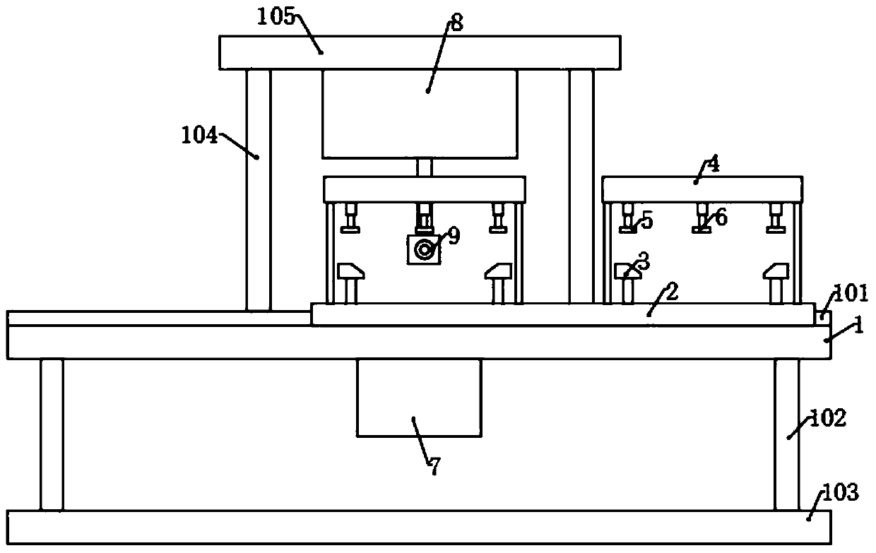
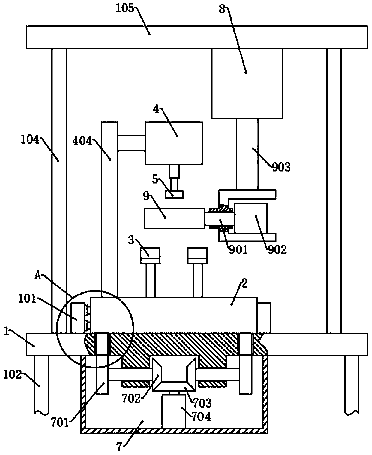
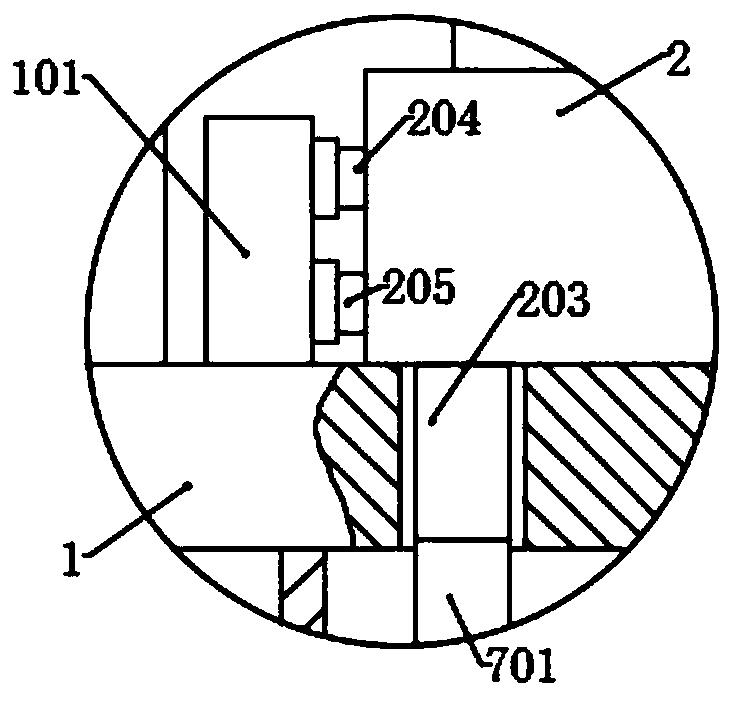
[0034] Please refer to the accompanying drawings, the present invention provides a technical solution: a mechanical arc-shaped workpiece grinding machine, including a workbench 1, a positioning mechanism, a drive box 7, an adjustment box 8 and a grinding assembly, and the four corners of the bottom surface of the workbench 1 are fixed There is a lower support rod 102, and a base 103 is fixed through the lower support rod 102. The drive box 7 is fixed in the middle of the bottom surface of the workbench 1, and the drive box 7 is provided with a driving mechanism, and the four corners of the top surface of the workbench 1 are fixed with upper Support rod 104, and is fixed with top plate 105 by upper support rod 104, and adjusting box 8 is fixedly connected with top plate 105, is provided with adjusting mechanism in adjusting box 8, and polishing assembly is connected with adjusting mechanism correspondingly, and the top surface of workbench 1 is also parallel Two limiting plates ...

Embodiment 2

[0042] On the basis of Embodiment 1, two sets of adjustment slots are provided on the positioning plate 2 corresponding to two sets of positioning blocks 3, each set of adjustment slots includes a drive slot 202, and two moving slots 201 are respectively provided on both sides of the drive slot 202, The bottom ends of the four positioning blocks 3 are located in the corresponding moving slots 201 and are fixed with the moving blocks. The first screw rods are threaded in the moving blocks, and the inner ends of the first screw rods are inserted into the driving slots 202 and fixed There is a first bevel gear, the first bevel gear meshes with a second bevel gear, and the second bevel gear is connected with a fourth motor.

[0043] The working principle of this embodiment is basically the same as that of Embodiment 1, the difference is that before placing the arc-shaped workpiece, according to the size of the arc-shaped workpiece, the first bevel gear and the second bevel gear are...

Embodiment 3

[0045] On the basis of Embodiment 2, a controller is also included, and the first motor 704, the second motor 902, the third motor and the fourth motor are all electrically connected to the controller, and the first motor 704 and the second motor 902 are controlled by the controller , the speed, direction of rotation, start time and shutdown time of the third motor and the fourth motor, reasonably arrange the working hours of each motor, etc., to avoid problems such as excessive working or stopping time of various components caused by manual control, and inaccurate control.


PUM


Abstract

The invention discloses a mechanical arc-shaped workpiece polishing machine, and belongs to the technical field of mechanical part machining. The mechanical arc-shaped workpiece polishing machine comprises a workbench, a positioning mechanism, a driving box, an adjusting box and a polishing assembly. An arc-shaped workpiece is placed on one of positioning blocks, a positioning plate is moved through a driving mechanism, the arc-shaped workpiece sequentially passes through a middle pressing block, a side pressing blocks and a middle pressing block, which are in three fixing states, in the moving process to make the arc-shaped workpiece always kept in a fixed state in the polishing process, a curve guide rail of a lifting guide rail in an adjusting mechanism is consistent with the arc-shapedworkpiece in shape in the polishing process, a moving plate drives the lifting guide rail to move through a rotating second gear in order to make a polishing roller move relative to the curve guide rail, after the workpiece on one side is polished, a workpiece to be machined is placed, the other workpiece at the other side is polished according to the same principle, after the two workpieces areprocessed, the positioning plate returns to the initial position, the above processes are repeated to polish two workpieces.

Description

technical field [0001] The invention relates to the technical field of mechanical parts processing, in particular to a mechanical arc-shaped workpiece grinding machine. Background technique [0002] In the process of machine production, the process of changing the shape, size, position and nature of the production object to make it a finished or semi-finished product is called a process. It is an essential part of the production process. The process can be divided into casting, forging, stamping, welding, machining, assembly and other processes. The mechanical manufacturing process generally refers to the sum of the machining process of parts and the assembly process of machines. Other processes are called auxiliary processes. Processes, such as transportation, storage, power supply, equipment maintenance, etc. [0003] Among them, mechanical processing refers to the process of changing the external dimension or performance of a workpiece through a mechanical device, gener...

Claims


Application Information

Patent Timeline
Patent Type & Authority Applications(China)
IPC IPC(8): B24B19/26B24B9/04B24B41/06B24B41/02
CPCB24B9/04B24B19/26B24B41/02B24B41/06
Inventor 王学荣
Owner 南京哈维斯特精密机械有限公司
Learn More