Battery mounting structure of electric vehicle

An installation structure, a technology for electric vehicles, applied in vehicle components, rider drive, transportation and packaging, etc., can solve problems such as increased manufacturing cost, falling off, narrow space, etc., to facilitate repair and maintenance, reduce longitudinal height, reduce The effect of taking up space

Inactive Publication Date: 2012-01-25
DAHON TECH
View PDF2 Cites 2 Cited by
  • Summary
  • Abstract
  • Description
  • Claims
  • Application Information

AI Technical Summary

Problems solved by technology

[0002] The battery installation position of the electric vehicle is related to the arrangement of the electrical connecting wires, and even affects the appearance of the electric vehicle. It is known that a battery is installed on the seat tube of the electric vehicle near the rear fork. Among them, it is not convenient for quick assembly or disassembly, nor is it convenient for inspection and maintenance or repair work; another battery installation structure installs the battery on the hanger, and when the seat tube is lowered, the seat cushion interferes with the battery; other battery installation structures, such as the Chinese patent Document 200520046348.0 discloses an electric bicycle battery installation structure installed on the frame beam. The battery has a certain weight, which may cause the battery to slide or fall off after long-term use, and the rider’s legs may touch the battery during riding; China Patent document 200820142206.8 discloses a battery plug-in bicycle rear hanger. The battery is inserted into the bottom of the frame hanger body along the slideway slot. Because the battery has a certain thickness, the hanger will inevitably rise. When the weight is loaded, the center of gravity of the electric bicycle will move upward. , increase the instability of the electric bicycle, at the same time, heavy objects may press the battery box
If special materials are used, it is bound to increase the manufacturing cost

Method used


Image

  • Battery mounting structure of electric vehicle
  • Battery mounting structure of electric vehicle
  • Battery mounting structure of electric vehicle

Examples


Embodiment Construction

[0035] The present invention will be further described below in conjunction with the accompanying drawings.

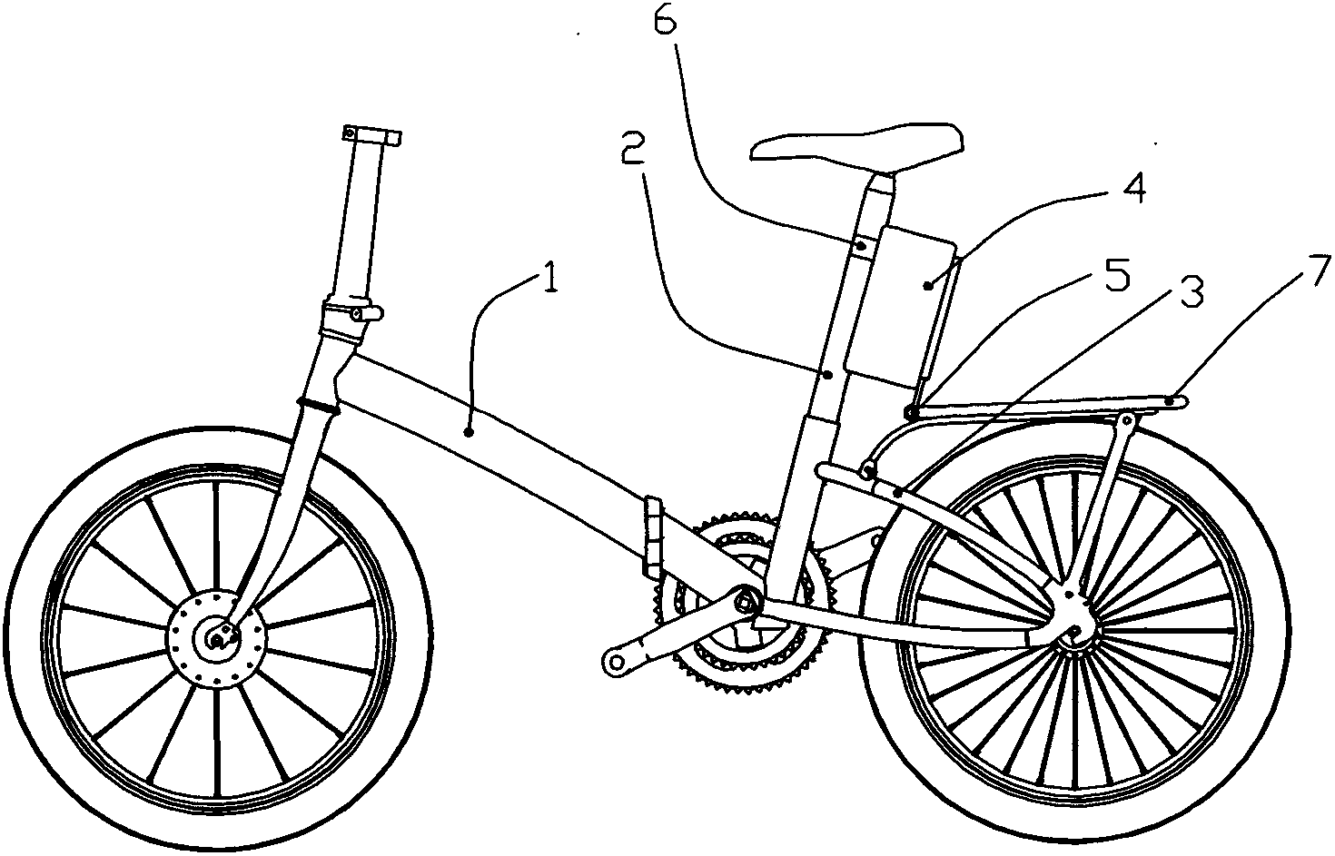
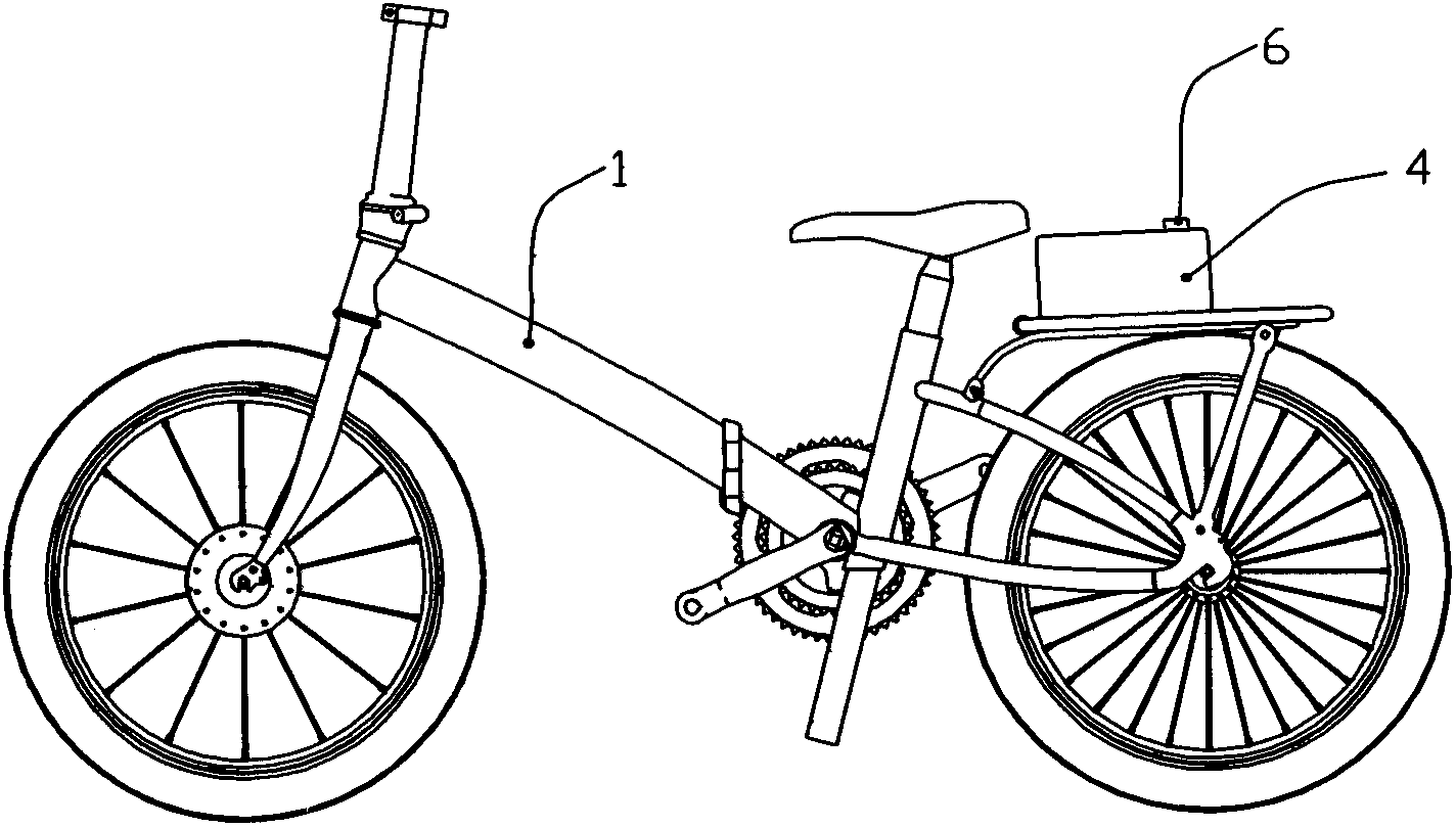
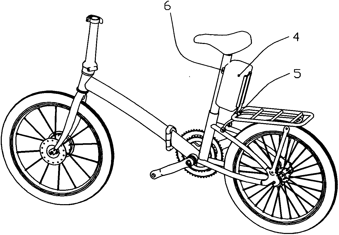
[0036] Electric vehicle comprises vehicle frame 1, front tube, front fork, seat tube 2, rear fork 3, front wheel, rear wheel, electric motor and battery, and battery installation structure disclosed by the present invention comprises a seat body 4 that accommodates battery, can adopt battery Pack the batteries in the box and put them into the base 4. The battery can be directly loaded into the base 4. In a word, the battery can be disassembled in the base 4 at will for replacement, repair and maintenance. One end of the base 4 is provided with The pivoting part 5 is rotatably connected to the supporting member provided on the electric vehicle.

[0037] Such as Figure 1-6 As shown, the rear fork 3 of the electric vehicle is provided with a bracket supporting the pivoting portion 5, the bracket is the support member, the pivoting portion 5 is arranged on the bracket, a...


PUM


Abstract

The invention discloses a battery mounting structure of an electric vehicle, in particular to a battery mounting structure with convenience for assembly and disassembly. The battery mounting structure comprises a seat body for containing a battery, wherein a pivoting section is arranged at one end of the seat body; the pivoting section is rotatably connected with a supporting member arranged on the electric vehicle; and the seat body is arranged on a seat tube. The battery mounting structure of the electric vehicle, disclosed by the invention, is mounted on the seat tube, is convenient to mount and dismount, and provides convenience for battery repairing and maintenance; when the seat tube is lowered for storage, the seat body can be rotated to the rear side, and a cushion cannot be in interference with the battery.

Description

technical field [0001] The invention relates to a battery installation structure of an electric vehicle, in particular to a battery installation structure which is convenient for assembly and disassembly. Background technique [0002] The battery installation position of the electric vehicle is related to the arrangement of the electrical connecting wires, and even affects the appearance of the electric vehicle. It is known that a battery is installed on the seat tube of the electric vehicle near the rear fork. Among them, it is not convenient for quick assembly or disassembly, nor is it convenient for inspection and maintenance or repair work; another battery installation structure installs the battery on the hanger, and when the seat tube is lowered, the seat cushion interferes with the battery; other battery installation structures, such as the Chinese patent Document 200520046348.0 discloses an electric bicycle battery installation structure installed on the frame beam. ...

Claims


Application Information

Patent Timeline
Patent Type & Authority Applications(China)
IPC IPC(8): B62M6/90
CPCB62M6/90
Inventor 萧启明韩德玮杜友林
Owner DAHON TECH
Why Eureka
Try Eureka