Aluminium electrolysis cell anode carbon block

An anode carbon block and aluminum electrolytic cell technology, which is applied in the field of aluminum electrolysis, can solve the problems of uneven discharge of anode gas, destruction of the original anode, high current density, etc., so as to avoid falling off of small single anodes, reduce discharge resistance and local resistance. big effect

Inactive Publication Date: 2012-01-25
冯乃祥
View PDF3 Cites 3 Cited by
  • Summary
  • Abstract
  • Description
  • Claims
  • Application Information

AI Technical Summary

Problems solved by technology

[0008] 2. The manufacturing process technology of small anode monomers is relatively complicated, which requires major changes to the current anode molding, roasting and loading out of the furnace, as well as the anode assembly process and equipment
Such as remodeling or rebuilding, resulting in a decrease in productivity and an increase in investment
If the current anode is used, the installed whole carbon anode is divided into several small anodes by sawing, which is also easy to cause damage to the original anode; in addition, after the block is replaced, the insulation material covering the anode enters the When it is in the gap between small anodes, it may also form a certain resistance to the escape of anode gas, or make the anode gas discharge uneven
[0009] 3. The current density of the anode steel carbon part of the current electrolytic cell is too high, and the density of the anode carbon around the anode carbon bowl is low, which is one of the main reasons for the high anode voltage drop at the anode steel carbon part

Method used


Image

  • Aluminium electrolysis cell anode carbon block
  • Aluminium electrolysis cell anode carbon block
  • Aluminium electrolysis cell anode carbon block

Examples


Embodiment 1

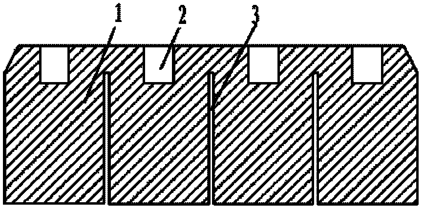
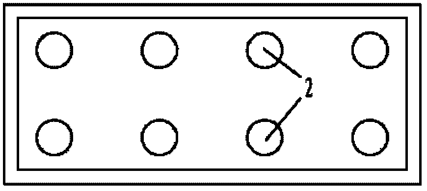
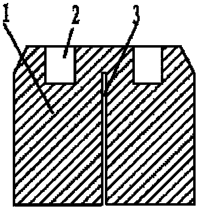
[0036] Such as figure 1 , figure 2 , image 3 As shown, in this embodiment 1, the upper surface of the anode carbon block is provided with 2 rows of carbon bowls, each row has 4, 2 rows of 8 carbon bowls in total, the depth of the carbon bowls is 100-200mm, and the inner diameter is 100 mm. ~200mm, the width of the anode substrate is 600~800mm, and the length is 1500~2000mm. In the longitudinal direction of the anode, there are three slots perpendicular to the longitudinal direction of the anode between the upper surface of the carbon block 50-200mm below the upper surface of the carbon block in the middle of the two adjacent carbon bowls in the front and back rows to the bottom palm of the anode. The width of the groove is 10-30mm, and the length of the groove is the same as the width of the anode.

[0037] There is also a slot with a width of 10-30mm between the upper surface of the anode carbon block and the bottom palm of the anode between the upper surface of the anod...

Embodiment 2

[0039] Such as Figure 4 , Figure 5 , Image 6 shown. In this embodiment 2, the upper surface of the anode carbon block is provided with 2 rows of carbon bowls, each row has 4, 2 rows of 8 carbon bowls in total, the depth of the carbon bowls is 100-200mm, and the inner diameter is 100-200mm. The width of the anode substrate is 600-800mm, and the length is 1500-2000mm. In the longitudinal direction of the anode, there are three slots perpendicular to the longitudinal direction of the anode between the upper surface of the carbon block 50-200mm below the upper surface of the carbon block in the middle of the two adjacent carbon bowls in the front and back rows to the bottom palm of the anode. The width of the groove is 10-30mm, and the length of the groove is the same as the width of the anode substrate.

[0040] Example 2 differs from example 1 in that there are no grooves in the longitudinal direction of the carbon anode.

Embodiment 3

[0042] Such as Figure 7 , Figure 8 , Figure 9shown. In this embodiment 3, the upper surface of its anode carbon block is provided with 2 rows of carbon bowls, each row has 4, 2 rows of 8 carbon bowls in total, the depth of the carbon bowls is 100-200mm, and the inner diameter is 100-200mm. The width of the anode substrate is 600-800mm, and the length is 1500-2000mm. In the longitudinal direction of the anode, there are three slots perpendicular to the longitudinal direction of the anode between the upper surface of the carbon block 50-200mm below the upper surface of the carbon block in the middle of the two adjacent carbon bowls in the front and back rows to the bottom palm of the anode. The width of the groove is 10-30mm, and the length of the groove is the same as the width of the anode substrate.

[0043] In the transverse direction of the anode carbon block, there is a slot in the longitudinal direction between the upper surface of the carbon block 50-200mm below t...


PUM

PropertyMeasurementUnit
depthaaaaaaaaaa
widthaaaaaaaaaa
lengthaaaaaaaaaa

Abstract

The invention discloses an aluminium electrolysis cell anode carbon block. The upper surface of the anode carbon block is a plane, wherein the plane of the upper surface of the anode carbon block is provided with concave carbon bowls connected with steel talons below an anode guide rod; the carbon bowls are arranged in one row or two rows at equal distances along the length direction of the anode carbon block, and each row comprises 2-4 carbon bowls; and a groove is arranged from the position which is 50-200mm below the upper surface of the anode carbon block in the middle of two adjacent carbon bowls on the anode carbon block to an anode bottom palm. According to the aluminium electrolysis cell anode carbon block, CO2 gas generated on the bottom surface of the anode in the electrolysis process can be smoothly discharged into a space formed by the upper surface of an electrolyte melt to the top of the groove in the whole anode working period or during most time; and when the upper part of the top of a lateral groove in the middle of the length direction of the carbon anode is provided with a vertically through narrow slit, the narrow slit has the function of reducing anode end tip damage because the narrow slit releases expansion force on the carbon anode connected with the anode steel talons on the end part by the thermal expansion of the beam with the upper steel talons of the anode in the electrolytic cell at a high temperature.

Description

technical field [0001] The technology of the present invention belongs to the technical field of aluminum electrolysis, and in particular relates to a method that enables the anode gas of an aluminum electrolytic cell to quickly escape from the bottom of the anode, reduces the secondary reaction between the anode gas and the dissolved metal aluminum in the electrolyte melt, and increases the current of the aluminum electrolytic cell. efficient anode. Background technique [0002] Industrial aluminum electrolytic cells have two important technical and economic indicators, one is power consumption, and the other is current efficiency. The relationship between power consumption and current efficiency is inversely proportional. Improving current efficiency can reduce the power consumption of aluminum electrolysis production. The relationship between the two The relationship can be expressed by the following formula: [0003] [0004] In industrial aluminum electrolytic produ...

Claims


Application Information

Patent Timeline
Patent Type & Authority Applications(China)
IPC IPC(8): C25C3/12
Inventor 冯乃祥
Owner 冯乃祥
Why Eureka
Try Eureka