Method for testing characters of micro piles in landslide control

A test method and technology of micro piles, which are applied in the test of infrastructure, construction, infrastructure engineering, etc., can solve the problem that the reliability of calculation results needs to be further discussed.

Inactive Publication Date: 2012-01-25
INST OF GEOMECHANICS
View PDF1 Cites 16 Cited by
  • Summary
  • Abstract
  • Description
  • Claims
  • Application Information

AI Technical Summary

Problems solved by technology

[0009] For method 2, since the parameters used in the calculation process are usually determined by human subjective factors, the credibility of the calculation results obtained by this method needs to be further discussed

Method used


Image

  • Method for testing characters of micro piles in landslide control
  • Method for testing characters of micro piles in landslide control
  • Method for testing characters of micro piles in landslide control

Examples


Embodiment 1

[0036] Embodiment 1, the test method of the micropile character in landslide prevention and control.

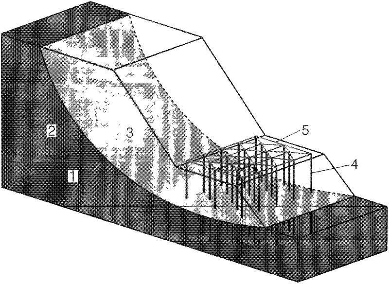
[0037] The present invention first needs to set up a large-scale physical landslide model, and the physical landslide model includes: a sliding bed, a sliding surface, a sliding body, and a plurality of micro piles and a plurality of monitoring devices arranged therein. The above-mentioned sliding bed and sliding body can be arranged mainly by layered filling with soil as the medium, and the above-mentioned micro piles can be prefabricated piles (such as reinforced concrete prefabricated piles, etc.). Secondly, loading on the slope top of the successfully set physical landslide model, and obtaining the data of each monitoring device, the slide of the landslide under loading is helpful for the study of the behavior of the micropile in the whole process from stress to failure under the action of the landslide. Finally, after the loading is stopped, section excavation can be car...

Embodiment 2

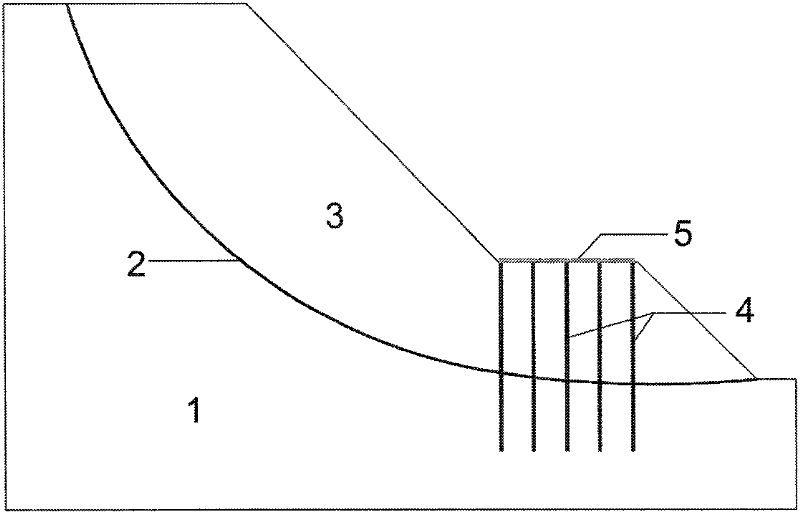
[0074] Embodiment two, the test method of the micropile character in landslide prevention and control. Attached below Figures 1 to 3 The test method will be described.

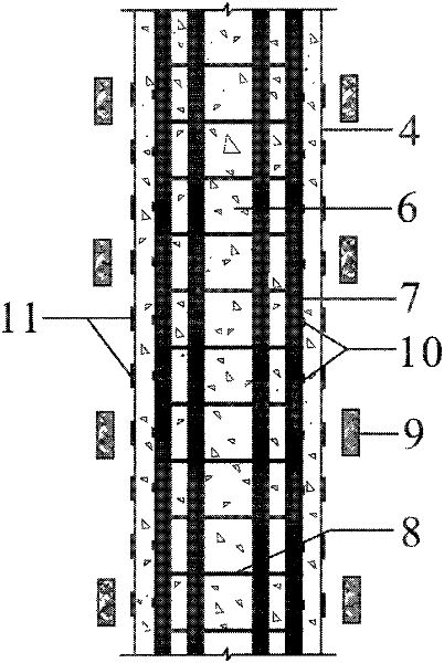
[0075] Step 1. Carry out experimental design. Specifically, according to the conditions of the test site and the similarity theory, the landslide model (including the model of the sliding bed 1 and the sliding body 3) and the micro-pile model (including the micro-pile 4, strain gauges 10 and 11, and earth pressure cell) in the test were designed. 9, the miniature pile top connection beam 5 and the model including the pile top displacement monitoring device).

[0076] In order to ensure the smooth progress of the test, when designing the landslide model, it should be ensured that the stability coefficient of the landslide model is between 1.0 and 1.1 without micro-piles, that is, the landslide model is in a basically stable state. As for too large, so as to avoid increasing the difficulty of the test. Para...


PUM


Abstract

The invention relates to a method for testing characters of micro piles in the landslide control. The method comprises the following steps of: manufacturing a landslide bed in a filling mode; excavating a plurality of micro pile grooves on the landslide bed and placing the micro piles with micro pile stress monitoring devices in the micro pile grooves, wherein one or a plurality of micro piles are arranged in each micro pile groove; filling the micro pile grooves in a layered mode and placing horizontal pressure monitoring devices at the position at a first distance from the corresponding micro piles in the layered filling process; placing a sliding film on a sliding surface of the landslide bed, filling the sliding film in a layered mode to form a slip mass, and placing the horizontal pressure monitoring devices at the positions at a second distance from the corresponding micro piles in the process of filling the slip mass; manufacturing a slope and arranging pile cap beams and pile top displacement monitoring devices on the slip mass; and loading and acquiring monitored data output by each monitoring device at the top of the slope. Due to the adoption of the method, the characters of the micro piles in the actual using process can be accurately acquired, so that the micro piles are beneficial for being popularized and applied in the landslide control.

Description

technical field [0001] The invention relates to a micropile technology, in particular to a method for testing the properties of the micropile in landslide prevention and control. Background technique [0002] Due to its characteristics of non-excavation construction, small disturbance to the slide body, and fast construction speed, micropiles have been more and more used in landslide prevention and control, especially landslide emergency rescue. [0003] Due to the small pile diameter and large length-to-diameter ratio of the micropile, the bending stiffness of the single pile is low. Therefore, in practical applications, the form of pile groups is usually used for anti-sliding. In the process of landslide prevention and control, the design method of pile groups is usually involved. However, due to the complexity of the pile-soil interaction mechanism and the lack of a clear understanding of it, there is no objective and mature design method. Therefore, the micro There is s...

Claims


Application Information

Patent Timeline
Patent Type & Authority Applications(China)
IPC IPC(8): E02D33/00
Inventor 殷跃平闫金凯门玉明李滨肖尤元贺模红
Owner INST OF GEOMECHANICS
Why Eureka
Try Eureka