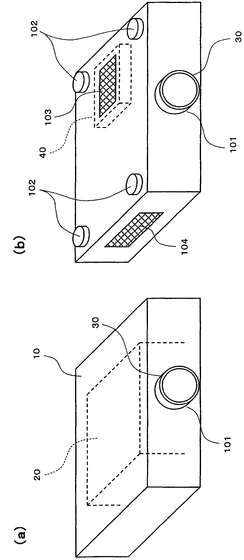
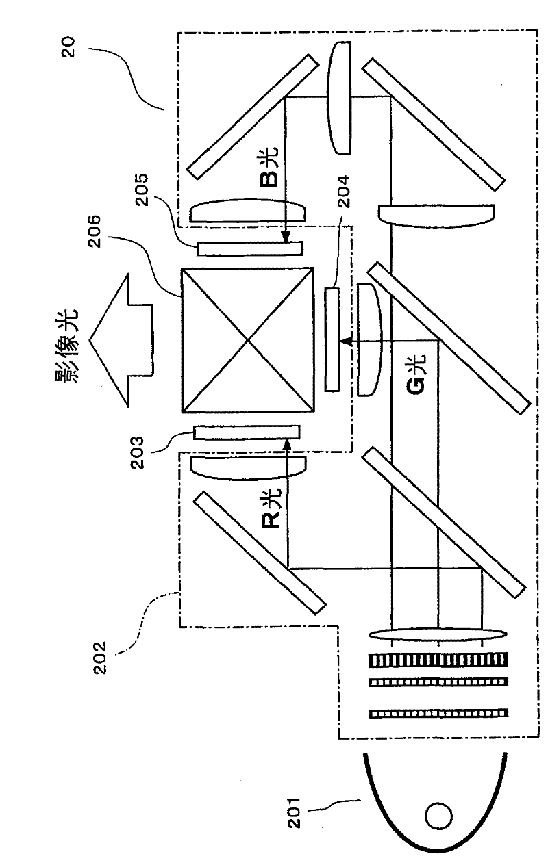
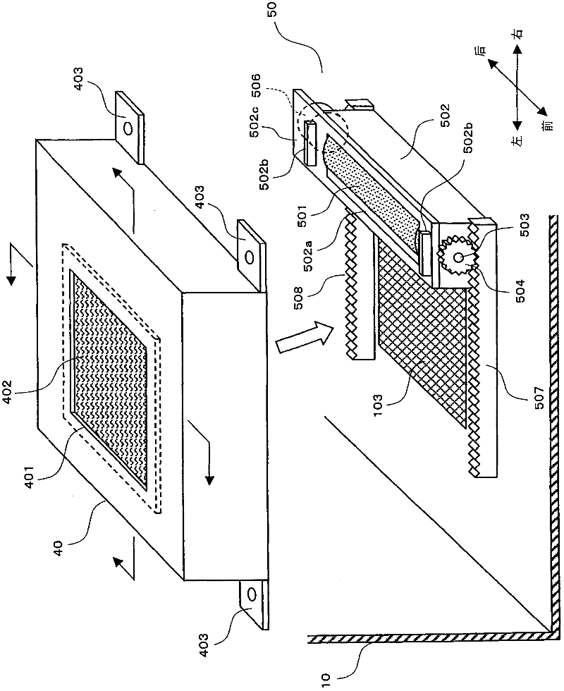
Electrical apparatus and projection display device with particle filter

A technology for electrical equipment and suction devices, which is applied in the fields of electrical equipment and projection display devices, and can solve problems such as the removal of unnecessary substances that cannot be removed by the removal device

Inactive Publication Date: 2012-01-25
SANYO ELECTRIC CO LTD
View PDF5 Cites 2 Cited by
  • Summary
  • Abstract
  • Description
  • Claims
  • Application Information

AI Technical Summary

Problems solved by technology

[0008] However, in this case, since the filter is kept in a state of suction due to suction, it is difficult for the attached unnecessary substances to escape from the filter.
In this case, there is a possibility that the removal of unnecessary substances cannot be performed satisfactorily by the removal device.

Method used


Image

  • Electrical apparatus and projection display device with particle filter
  • Electrical apparatus and projection display device with particle filter
  • Electrical apparatus and projection display device with particle filter

Examples


change example

[0084] Figure 7 It is a figure for demonstrating the automatic cleaning control of the filter which concerns on a modification. Figure 7 (a) is a figure which shows the processing flow of automatic cleaning control. Figure 7 (b) is a diagram showing the state of the drive voltage to the panel cooling fan 61 when the automatic cleaning control is executed.

[0085] In this modified example, the Figure 6 In the control process of (a), the process of step S107 is added. That is, in this modified example, after the cleaning of the filter 402 is completed, the control unit 801 Figure 7 As shown in (b), at the time of cleaning completion (T2), the drive voltage to the panel cooling fan 61 is increased (voltage V2→V0) more than before cleaning, and the rotation speed of the panel cooling fan 61 is increased more than before cleaning (S107). As a result, the air intake from the air intake port 103 increases compared to the state in which the panel cooling fan 61 has returned ...


PUM


Abstract

An electrical apparatus includes an air intake device which draws air into an apparatus body; a controller which controls the air intake device; a filter which removes unwanted matter from the air drawn into the apparatus body; and a removing device which removes the unwanted matter adhered to the filter. In this arrangement, the controller controls the air intake device to lower an air intake rate of the filter when the removing device is operated.

Description

technical field [0001] The present invention relates to an electric device and a projection display device provided with a filter. Background technique [0002] In electrical equipment such as projectors, air conditioners, and air cleaners, which suck the outside air into the equipment, a filter is detachably arranged at the suction port in order to remove unnecessary substances (dust, etc.) contained in the outside air. . [0003] Unnecessary substances that cannot pass through the filter adhere to the suction surface of the filter, and the filter will soon become clogged. In this case, it is impossible to properly inhale air into the device main body. Users need to clean the filter to remove the attached unnecessary substances. [0004] Cleaning of the filter is troublesome for the user. Therefore, in such electrical equipment, in order to reduce the user's troubles, a removing device that automatically removes unnecessary substances adhering to the filter may be used ...

Claims


Application Information

Patent Timeline
Patent Type & Authority Applications(China)
IPC IPC(8): G03B21/14G03B21/16B01D46/42B01D46/00H04N5/74
CPCB01D2279/45B01D46/0065B01D46/681
Inventor 小谷和范
Owner SANYO ELECTRIC CO LTD
Why Eureka
Try Eureka