Cleaning device

A technology of cleaning device and cleaning ring, which is applied to cleaning equipment, cleaning machinery, carpet cleaning, etc., can solve the problem of multiple cleaning of the mop, and achieve the effect of avoiding excessive humidity and reducing the frequency of cleaning

Inactive Publication Date: 2012-02-01
SHANGHAI MEIDIXIN ELECTRONICS TECH
View PDF0 Cites 2 Cited by
  • Summary
  • Abstract
  • Description
  • Claims
  • Application Information

AI Technical Summary

Problems solved by technology

[0003] In order to solve the technical problem that the existing mop needs to be cleane...

Method used


Image

  • Cleaning device
  • Cleaning device
  • Cleaning device

Examples


Embodiment 1

[0097] The cleaning device of this embodiment includes: a water tank 1, a water roller 10, a water squeezing body 9, a cleaning endless belt 6, a first supporting roller 21, a second supporting roller 22, and two rollers 23. They are explained separately below.

[0098] 1. Describe and explain the water tank 1.

[0099] The water tank 1 has a bottom 1-1, a front wall 1-2, a rear wall 1-3, a left wall 1-4, a right wall 1-5, a first bracket 26, and a second bracket 25, such as Figure 1 to Figure 7 Shown.

[0100] The cross-sectional shapes of the front upper edge 1-a and the rear upper edge 1-b of the water tank 1 are arc-shaped; the front wall 1-2 of the water tank 1 is provided with an inwardly protruding horizontal front strip 4 with an arc-shaped protruding surface. The position of the horizontal front strip 4 corresponds to the position of the front squeezing piece 9-1; the rear wall 1-3 of the water tank is provided with an inwardly protruding horizontal rear strip 4-1 with an ...

Embodiment 2

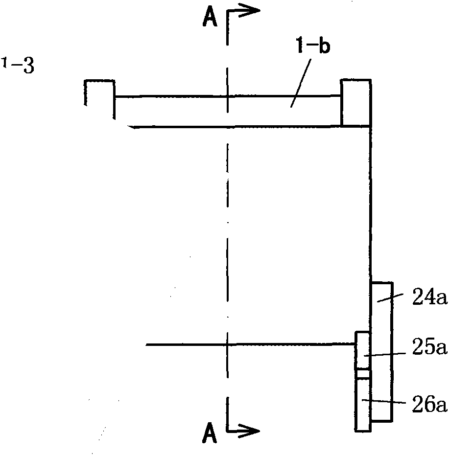
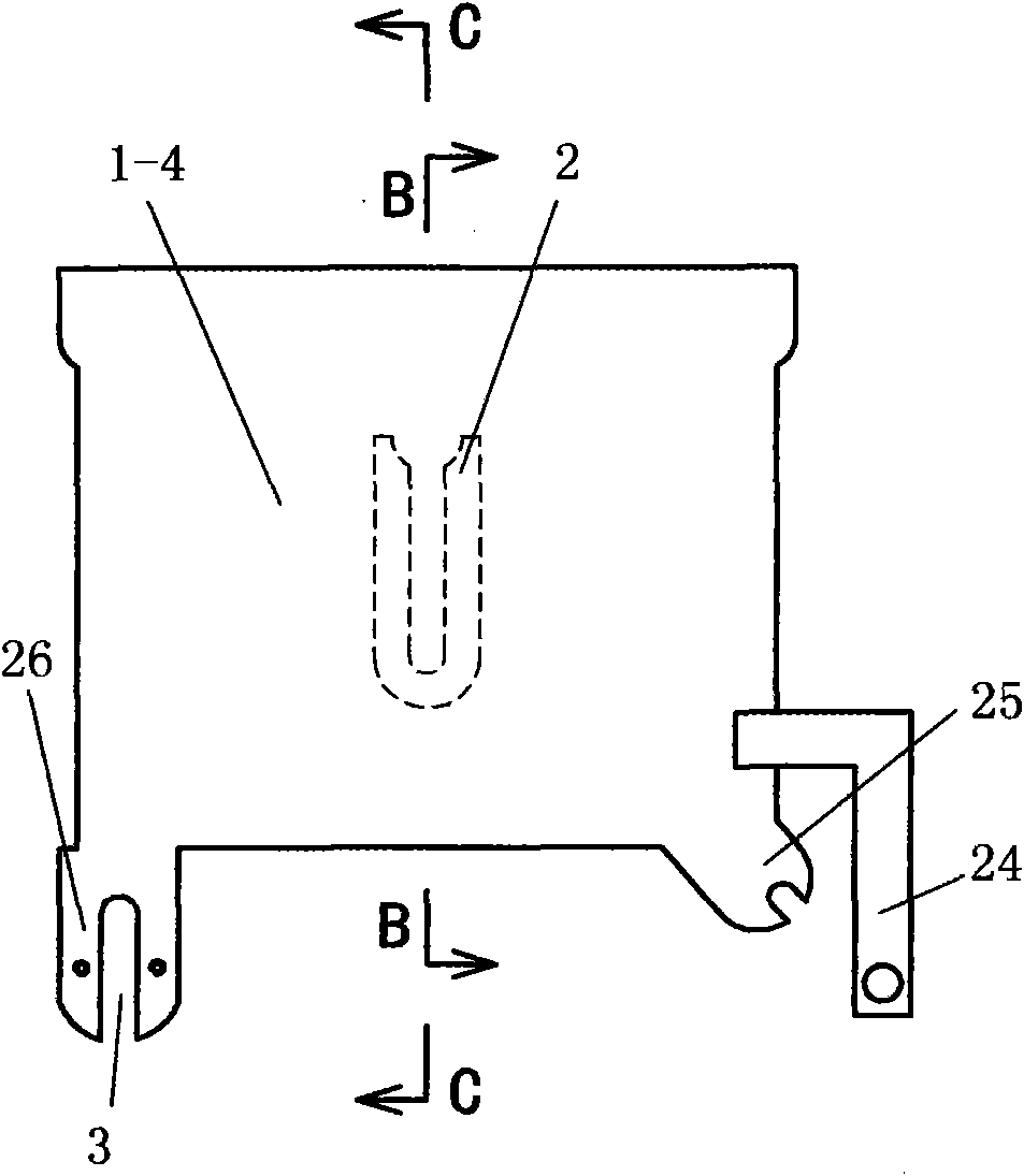
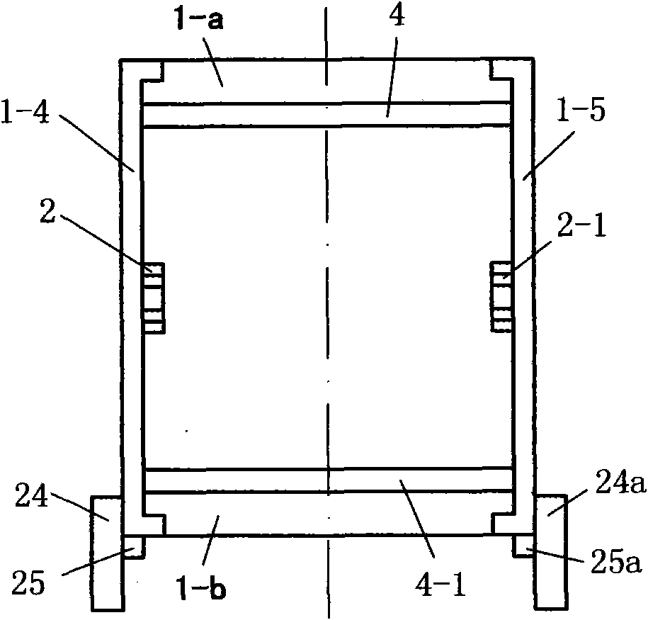
[0129] In this embodiment, the water tank 1 is manufactured in an integrated manner using plastic as the raw material; the water tank 1 is as Figure 1 to Figure 10 Shown. figure 1 Is the main view of the water tank; figure 2 Yes figure 1 Left view of image 3 Yes figure 1 Top view of Figure 4 Yes figure 1 The rear view; Figure 5 Yes figure 1 A-A cross-sectional view; Image 6 Yes figure 2 B-B cross-sectional view; Figure 7 Yes figure 2 C-C cross-sectional view; Figure 8 It is a partial three-dimensional schematic diagram, expressing the situation of the bearing body on the left wall of the water tank; Picture 9 Is a three-dimensional schematic diagram of the cover; Picture 10 It is a partial three-dimensional schematic diagram of the water tank.

[0130] The water tank 1 in this embodiment has a bottom 1-1, a front wall 1-2, a rear wall 1-3, a left wall 1-4, a right wall 1-5, a first bracket 26, a second bracket 25, and a bearing Block 2.

[0131] The cross-sectional shap...

Embodiment 3

[0137] Using rubber or plastic as raw materials, the cleaning ring belt 6 is manufactured, and the manufactured cleaning ring belt 6 as a stand alone, before being installed on the device, presents a circular ring shape without seams.

[0138] In the present invention, the position of the cleaning endless belt 6 is: the front upper edge 1-a of the water tank 1, between the front wall 1-2 of the water tank 1 and the front squeezing sheet 9-1, the water roller 10 facing The lower surface, between the rear wall 1-3 of the water tank 1 and the rear squeeze sheet 9-2, the upper rear edge 1-b of the water tank 1, the surface of the second support roller 22, and the surface of the first support roller 21. The above position is like Picture 11 with Figure 13 Shown.


PUM


Abstract

The invention relates to the technical field of environment protection and discloses a cleaning device. In order to solve the technical problem that the traditional mop needs to be washed a plurality of times during usage, the invention provides a technical scheme as follows: the cleaning device is characterized by comprising a water tank (1), an in-water roll (10), a water extruding body (9), a cleaning endless belt (6), a first supporting roll (21), a second supporting roll (22), and two rollers (22); the first supporting roll (21) is arranged in the front of the lower side of the water tank (1) and is rotationally connected with the water tank (1); the second supporting roll (22) is arranged at the rear part of the lower side of the water tank (1) and is rotationally connected with the water tank (1); the in-water roll (10) is arranged inside the water tank (1), and two ends of the in-water roll (10) are rotationally connected with a left wall (1-4) and a right wall (1-5) of the water tank (1); and the in-water roll (10) and a round roll (9-4) are in frictional contact, or, the in-water roll (9), the water extruding body (9) and the round roll (9-4) are provided with teeth (10-2 and 9-3) which are mutually meshed or embedded. The cleaning device disclosed by the invention ahs the beneficial effects that no cleaning is needed when an operation area of a medium area is cleaned, and the like.

Description

Technical field [0001] The present invention relates to the technical field of environmental protection, in particular to a cleaning device. Background technique [0002] Mops are usually used to clean floors, concrete floors, vehicle and ship passages, etc., to remove dirt and dust by mopping. While the mop in the prior art brings convenience to people, it also has some shortcomings; for example, in the process of mopping a large area, the mop needs to be cleaned many times. Summary of the invention [0003] In order to solve the technical problem that the existing mop needs to be cleaned multiple times during use, the present invention proposes the following technical solutions. [0004] 1. A cleaning device comprising: a water tank, a water roller, a water squeezing body, a cleaning endless belt, a first supporting roller, a second supporting roller, and two rollers; [0005] The water tank has a bottom, a front wall, a rear wall, a left wall, and a right wall; [0006] The first ...

Claims


Application Information

Patent Timeline
IPC IPC(8): A47L13/20A47L13/59
Inventor 梁怀清
Owner SHANGHAI MEIDIXIN ELECTRONICS TECH
Why Eureka
Try Eureka