Press mechanism and bonding apparatus

A technology of a pressurizing device and a joining device, which is applied in the directions of presses and manufacturing tools, can solve the problems of complicated vacuum device structure and vacuum control method, etc.

Active Publication Date: 2012-02-01
MURATA MFG CO LTD
View PDF5 Cites 5 Cited by
  • Summary
  • Abstract
  • Description
  • Claims
  • Application Information

AI Technical Summary

Problems solved by technology

Each small chamber is evacuated separately, which makes the structure of the vacuum device and the vacuum control method complicated

Method used


Image

  • Press mechanism and bonding apparatus
  • Press mechanism and bonding apparatus
  • Press mechanism and bonding apparatus

Examples


Embodiment Construction

[0073] Hereinafter, a pressurizing mechanism and a joining device according to a first embodiment of the present invention will be described with reference to the drawings.

[0074] First, the pressurizing mechanism will be described.

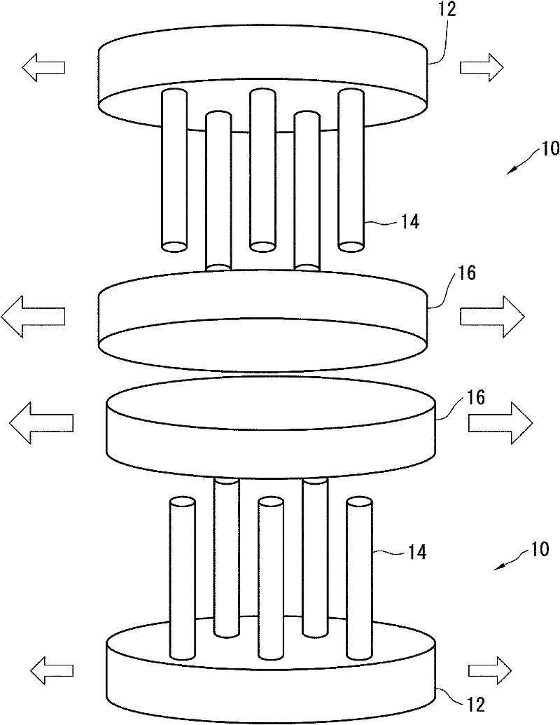
[0075] Such as figure 1 As shown, the press mechanism 10 has a base portion 12 of a floating handle structure. Here, the floating handle structure is a well-known mechanical structure, which has a handle frame and a crown, and is a structure in which the upper part of the crown is hooked to the groove of the handle frame. figure 1 The arrows in the arrows indicate the thermal expansion directions of the constituent members of the pressurizing mechanism 10 .

[0076] A plurality of supporting parts 14 are fixed on the base part 12 . The supporting part 14 is constituted by a pillar like a pin, and plays a role in making the pressurizing device ( figure 1 (not shown in ) acts to transmit the load applied to the base portion 12 to the heat ...


PUM


Abstract

The invention provides a press mechanism and a bonding apparatus improving treatment efficiency of a composite substrate and capable of preventing quality difference. A joint device (20) in the press mechanism and bonding apparatus is provided with: a base part (26, 30) with specified load applied by a press device (24), heat disc parts (40A-40E) provided with a heating device, and a supporting part (28, 32), the supporting part (28, 32) makes the load applied upon the base part (26, 30) be transmitted to the heat disc parts (40A-40E) as a press force, the top part of the supporting part is a free end no fixed with the heat disc part (40A-40E). Wherein, a plurality of heat disc parts (40A-40E) are disposed in the acting direction of the press force, via mutual press joint of the adjacent heat disc parts along the acting direction of the press force, vacuum chambers (62A-62D) are made to form between the heat disc parts, and base materials for adhesion are in heat press and joint in the vacuum chambers (62A-62D).

Description

technical field [0001] The present invention relates to a pressurizing mechanism for applying a predetermined pressure to a plate-shaped or sheet-shaped adhesive base material, and a method for manufacturing a composite substrate by joining a plurality of plate-shaped or sheet-shaped adhesive base materials by thermocompression bonding Engagement device. Background technique [0002] The existing pressurization device is a structure in which a supporting part (such as a screw, etc.) is used to fix the support and the heat insulating material between the floating mold shank (base) and the pressurizing plate (heating plate) that transmit the load (see below). Paragraph [0028] of Patent Document 1 and figure 2 Wait). [0003] Existing vacuum device is, the structure (referring to paragraph [0015] and figure 1 Wait). [0004] prior art literature [0005] [Patent Document 1] Japanese Patent Application Laid-Open No. 2006-136916 [0006] [Patent Document 2] Japanese Patent...

Claims


Application Information

Patent Timeline
Patent Type & Authority Applications(China)
IPC IPC(8): B29C65/02
CPCB30B5/02B30B7/02B30B15/064B29C43/10B29C43/18B29C43/56B29C65/02B29C66/00145B29C2043/189B29C2043/561
Inventor 福永茂树山根茂树中岛航横田光正
Owner MURATA MFG CO LTD
Why Eureka
Try Eureka