Transmission device of foot-operated washing machine
A transmission device and washing machine technology, which is applied to washing devices, washing machines with containers, textiles and papermaking, etc. It can solve the problems of complex structure, high maintenance rate, easy damage, etc., and achieve the effect of low speed and high speed in the dehydration process
- Summary
- Abstract
- Description
- Claims
- Application Information
AI Technical Summary
Problems solved by technology
Method used
Image
Examples
Embodiment 1
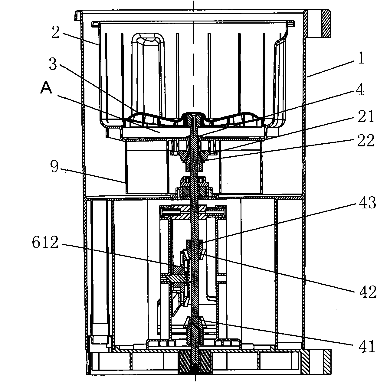
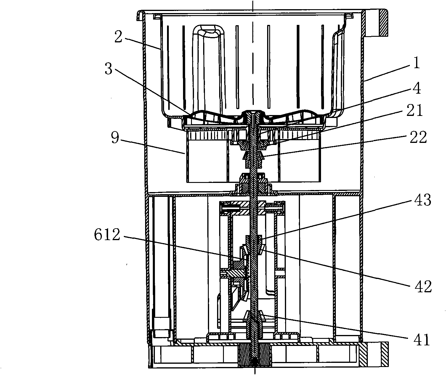
[0037] Such as Figure 2 to Figure 4 As shown, below the inner tub 2, there is a buoy 9 that can make the inner tub 2 float up during washing. The buoyancy drives the upward movement and the clothes and its own gravity move downward during dehydration. The buoy 9 drives the inner bucket 2 to float up and includes two stages. The first stage is that the buoy 9 first drives the inner bucket 2 to float up alone, and the pulsator 3 and the pulsator shaft 4 do not move. Between the bottom of the inner barrel 2 and the pulsator 3, there is an activity space A for the inner barrel 2 to float up alone. This stage corresponds to the separation of the inner spline 21 and the outer spline 22, and the inner barrel 2 and the pulsator shaft 4 are relatively free; the second stage is the buoy 9. Continue to drive the inner barrel 2 to float up, and at the same time drive the pulsator 3 and the pulsator shaft 4 to move upward. At this stage, the washing bevel gear 41 is meshed with the transm...
Embodiment 2
[0043] Such as Figure 5 As shown, the relationship between the inner spline at the bottom of the inner barrel and the outer spline on the pulsator shaft in this embodiment is: the pulsator shaft moves upward, the outer spline moves upward and separates from the inner spline, and vice versa moves downward and engages with the inner spline ( not shown in the figure). The bottom end of the pulsator shaft 4 is provided with a manual clutch device that enables the pulsator shaft 4 to move up and down. The manual clutch device 7 includes a clutch device base 70, a transmission plate 71 that can move along a horizontal direction on the clutch device base 70, and a drive transmission. Plate 71 horizontally moves the clutch button 72; one end of the drive plate 71 is provided with a resetting drive spring 73 and an inclined chute 74, and the other end is provided with an inclined slideway 75 and a gap at the bottom of the slideway 75 corresponding to the bottom end of the pulsator sha...
Embodiment 3
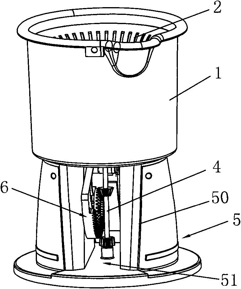
[0049] Such as Figure 6 As shown, the pedal device 6 described in this embodiment includes an arc-shaped plate 61, a pedal 62 that is integrated with the arc-shaped plate 61 and extends outward along its radius, and a reset torsion spring 63 that resets (see Figure 9 ), the base 5 is provided with a pair of external vertical openings 51 in the vertical direction, and the arc plate 61 is pivotally erected in the vertical openings 51 (see figure 1 ), the center of rotation is the center of circle of the arc-shaped plate, and it can rotate back and forth in the direction of the opening by relying on the pedal and the torsion spring to reset, similar to swinging, one end of the resetting torsion spring 63 is against the side wall of the vertical opening 51, and the other One end leans against the arc-shaped plate 61, and the pedal 62 extends from the vertical opening 51 to the outside of the base 5. The transmission tooth set includes a first drive bevel tooth 611 capable of eng...
PUM
 Abstract
Description
Claims
Application Information
 - R&D
- Intellectual Property
- Life Sciences
- Materials
- Tech Scout
- Unparalleled Data Quality
- Higher Quality Content
- 60% Fewer Hallucinations
Browse by: Latest US Patents, China's latest patents, Technical Efficacy Thesaurus, Application Domain, Technology Topic, Popular Technical Reports.
© 2025 PatSnap. All rights reserved.Legal|Privacy policy|Modern Slavery Act Transparency Statement|Sitemap|About US| Contact US: help@patsnap.com


