Steel-plastic composite drain pipe and production method thereof
A steel-plastic composite and drainage pipe technology, applied in the direction of pipes, rigid pipes, pipes/pipe joints/fittings, etc., can solve the problems of heavy unit weight, long bonding seam, easy water leakage of inner pipes, etc. The effect of improving quality and not easy to leak
- Summary
- Abstract
- Description
- Claims
- Application Information
AI Technical Summary
Problems solved by technology
Method used
Image
Examples
Embodiment 1
[0029] see figure 2 --10, the drainage pipe of this embodiment is composed of plates and belts 4 rotating and lapped to form an inner pipe. The key technology is that the outer surface of the plates and belts 4 has a protruding cavity 13, and the outer surface of the inner pipe is located between the cavities 13 Laying profiled steel 2, the cavity walls on both sides of the cavity 13 are in close contact with the side of the profiled steel, both sides of the profiled steel are pressed in the strip, the upper cavity wall of the cavity 13 constitutes the outer pipe 14 of the drain pipe, and the outer wall of the profiled steel 2 is covered with surface glue 1.
[0030] Its production method is:
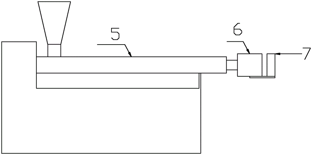
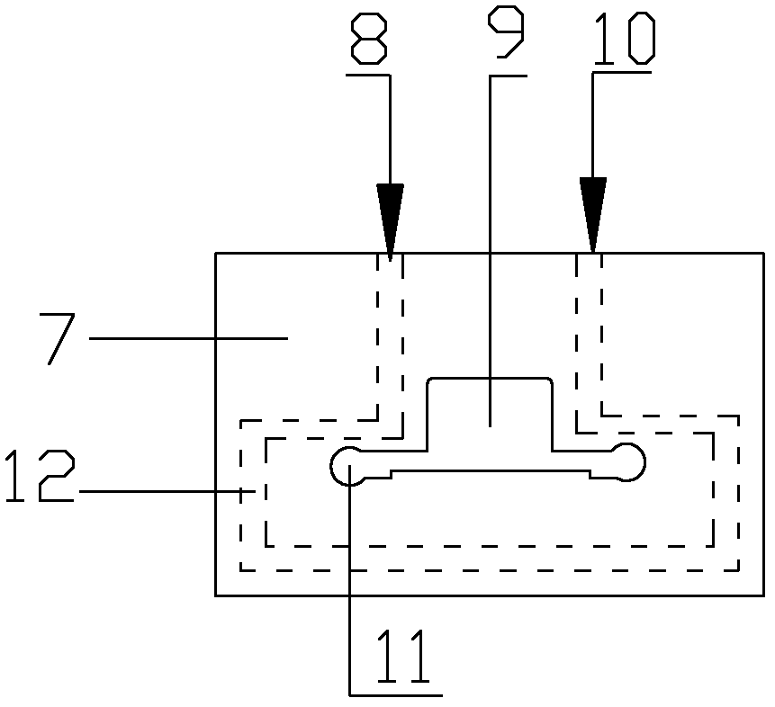
[0031] The extruder 5 extrudes the strip 4 through the mold 6, the two sides of the strip 4 are joints 3, the outer surface of the strip 4 has a protruding cavity 13, the strip 4 passes through the water jacket 7, and the water jacket 7 is in a A channel 9 is provided in the middle o...
Embodiment 2
[0034] see Figure 11 , 12 , the drainpipe of the present embodiment is formed inner pipe by the lap joint of plate 4 rotations, and its key technology is that the outer surface of plate band 4 has protruding cavity 13, and there are partition ribs 16 in the cavity to separate the cavity into two connected ones. One or more cavities, the outer surface of the inner pipe is located between the cavities 13 and the profile steel 2 is laid, the cavity walls on both sides of the cavity 13 are close to the side of the profile steel, and the two sides of the profile steel are pressed in the strip, the cavity 13 The upper cavity wall constitutes the outer pipe 14 of the drain pipe, and the outer wall of the shaped steel 2 is covered with a face glue 1 .
[0035] Its production method is the same as that of Embodiment 1, and the channel of the water jacket in this embodiment is adapted to the cross-sectional shape of the strip.
Embodiment 3
[0037] see Figure 13 , the drainpipe of the present embodiment is formed inner pipe by the rotating lap of strip 4, and its key technology is that the outer surface of strip 4 has protruding cavities, and the outer surface of the inner pipe is positioned between the cavities to lay profiled steel 2, the hollow After the cavity is rolled, the walls on both sides of the cavity are in close contact with the sides of the profiled steel.
[0038] Its production method is the same as that of Example 1, the difference is that the cavity is deformed by rolling with rollers 15, the cavity walls on both sides of the cavity are closely attached to the sides of the profiled steel, both sides of the profiled steel are pressed in the strip, and the upper cavity of the cavity The wall is close to the outer wall of the inner tube, and there is no cavity after compaction.
PUM
 Abstract
Description
Claims
Application Information
 - R&D
- Intellectual Property
- Life Sciences
- Materials
- Tech Scout
- Unparalleled Data Quality
- Higher Quality Content
- 60% Fewer Hallucinations
Browse by: Latest US Patents, China's latest patents, Technical Efficacy Thesaurus, Application Domain, Technology Topic, Popular Technical Reports.
© 2025 PatSnap. All rights reserved.Legal|Privacy policy|Modern Slavery Act Transparency Statement|Sitemap|About US| Contact US: help@patsnap.com


