Equipment for detecting circuit board defects based on visual detection method

A defect detection and visual detection technology, which is applied in the direction of optical defect/defect, sorting, etc., can solve the problems of unsatisfactory production, slow detection speed, long detection time, etc., and achieve short programming time, fast detection speed and adaptability Improved effect

Active Publication Date: 2012-02-01
科士恩科技(上海)有限公司
View PDF5 Cites 54 Cited by
  • Summary
  • Abstract
  • Description
  • Claims
  • Application Information

AI Technical Summary

Problems solved by technology

[0002] In the past, the detection of circuit board faults mainly relied on the manual detection method, which has defects such as easy missed detection, slow detection speed, and long detection time, which cannot meet the needs of production

Method used


Image

  • Equipment for detecting circuit board defects based on visual detection method
  • Equipment for detecting circuit board defects based on visual detection method
  • Equipment for detecting circuit board defects based on visual detection method

Examples


Embodiment Construction

[0025] The present invention will be further described below in conjunction with the accompanying drawings.

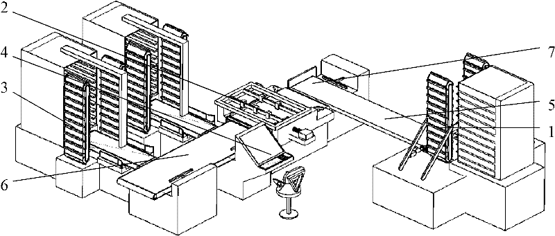
[0026] refer to Figure 1 to Figure 7 , a circuit board defect detection device, comprising a feeding module 1, a detection function module 2, a discharging module 3 and a control module 4, the feeding module is connected with a conveyor belt 5, and the feeding conveyor belt 5 is connected to the circuit board positioning mechanism 7 The detection function module 2 is connected, the detection function module is connected with the discharge module 3 through the discharge conveyor belt 6, and the control module controls the work of all the modules.

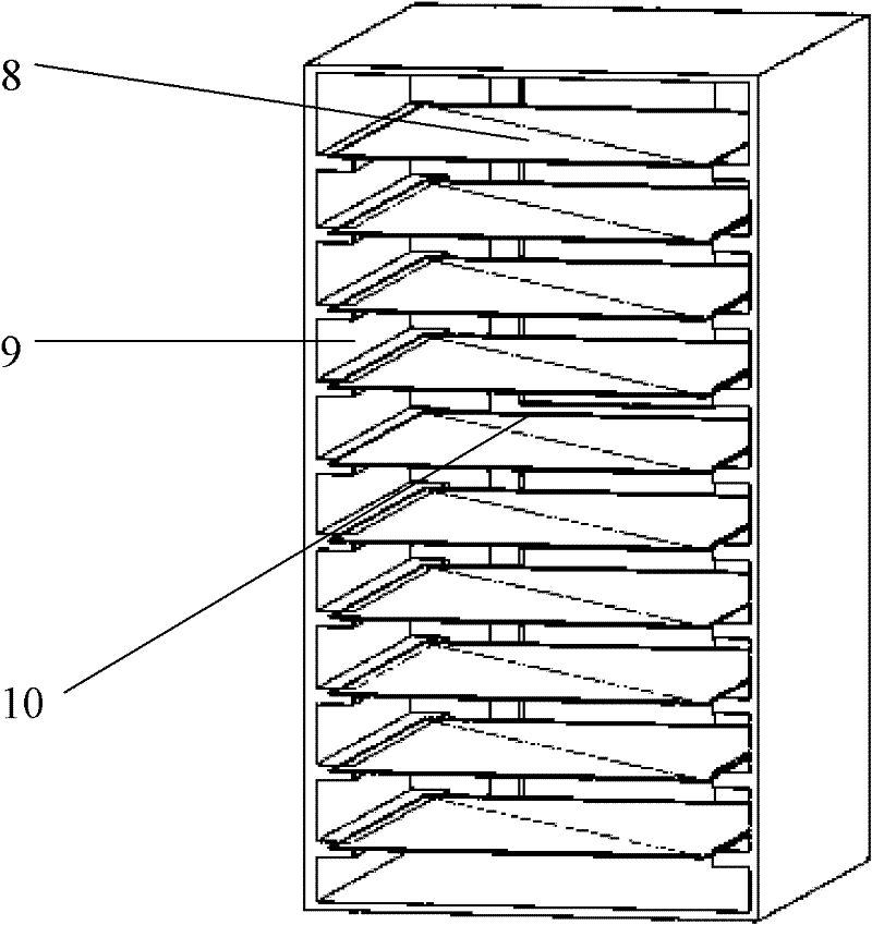
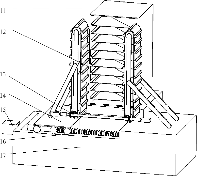
[0027] refer to figure 2 , when the loading frame 11 is fully loaded, it is composed of a loading frame shell 8, a loading frame push rod 9, and a circuit board to be detected 10, and corresponding equidistant material racks are installed on both sides of the inside of the loading frame shell. The push rod of the feeding ...


PUM


Abstract

The invention discloses equipment for detecting circuit board defects based on a visual detection method. The equipment comprises a material loading module, a detection function module, a material discharging module and a control module which is used for controlling a circuit board positioning mechanism to move and performing defect detection and discharge control, wherein the material loading module is connected with an inlet of a feeding conveying belt; the outlet of the feeding conveying belt is connected with the detection function module; the circuit board positioning mechanism is arranged at the outlet of the feeding conveying belt; the detection function module is connected with the material discharging module, and comprises a detection functional module base, a cameral pedestal provided with a charge-coupled device (CCD) camera, an electromagnet baffle plate and a detection conveying belt used for conveying the circuit board to be detected; the detection conveying belt is arranged on the detection function module base; the camera pedestal is positioned above the detection conveying belt; and the electromagnet baffle plate is arranged at the outlet of the detection conveying belt. By the equipment, the accuracy is improved, the detection speed is high, and the working efficiency is high.

Description

technical field [0001] The invention relates to a circuit board detection device, in particular to circuit board defect detection equipment. Background technique [0002] In the past, the detection of circuit board faults mainly relied on manual detection methods, which had defects such as easy missed detection, slow detection speed, and long detection time, which could not meet the needs of production. Contents of the invention [0003] In order to overcome the disadvantages of low accuracy, slow speed and low work efficiency of the existing circuit board detection methods, the present invention provides a circuit board defect detection based on visual detection method with improved accuracy, fast detection speed and high work efficiency equipment. [0004] The technical solution adopted by the present invention to solve its technical problems is: [0005] A circuit board defect detection device based on a visual detection method, the circuit board defect detection devi...

Claims


Application Information

Patent Timeline
Patent Type & Authority Applications(China)
IPC IPC(8): G01N21/88B07C5/36
Inventor 夏航
Owner 科士恩科技(上海)有限公司
Why Eureka
Try Eureka