
Semiconductor element and manufacturing method thereof

A manufacturing method and semiconductor technology, applied in the direction of semiconductor/solid-state device manufacturing, semiconductor devices, semiconductor/solid-state device components, etc., can solve the problems of electrode pad delamination, cracking, and electrode pads unable to withstand the stress of conductive elements, etc. The effect of optimal stress buffering effect

Inactive Publication Date: 2012-02-01
SILICONWARE PRECISION IND CO LTD
View PDF7 Cites 0 Cited by
  • Summary
  • Abstract
  • Description
  • Claims
  • Application Information

AI Technical Summary

Problems solved by technology

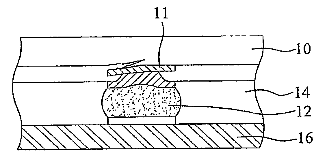
[0005] In view of the above-mentioned shortcomings of the prior art, the present invention provides a method for manufacturing a semiconductor element to solve the problem of the gap between the semiconductor silicon substrate, the electrode pad, the sealing material and the conductive element when the semiconductor element is heated in the prior art. The difference in thermal expansion coefficient is too large, so that the electrode pad cannot bear the stress caused by the conductive element, resulting in problems such as delamination or cracking of the electrode pad

Method used


Image

  • Semiconductor element and manufacturing method thereof
  • Semiconductor element and manufacturing method thereof
  • Semiconductor element and manufacturing method thereof

Examples


Embodiment Construction

[0032] The following examples further describe the technical means of the present invention in detail, but are not intended to limit the scope of the present invention.

[0033] It should be noted that the structures, proportions, sizes, etc. shown in the drawings attached to this specification are only used to match the content disclosed in the specification for the understanding and reading of those skilled in the art, and are not intended to limit the implementation of the present invention. Limiting conditions, so there is no technical substantive meaning, any modification of structure, change of proportional relationship or adjustment of size, without affecting the effect and purpose of the present invention, should still fall within the scope of the present invention. The disclosed technical content must be within the scope covered. At the same time, terms such as "upper, lower" and "one" quoted in this specification are only for the convenience of description, and are n...


PUM


Abstract

The invention discloses a semiconductor element and a manufacturing method thereof. The method is characterized by: forming a capping layer on a semiconductor silicon substrate whose surface is provided with electrode pads and a passivation layer so that the capping layer covers the electrode pads and partial passivation layer surrounding the electrode pads; forming a coating on the passivation layer and the capping layer, wherein a hole is formed on the coating and can reveal partial capping layer; forming a next metal layer on the capping layer which reveals the coating hole, wherein the next metal layer is electrically connected with the capping layer, and a diameter dimension of the next metal layer is less than or equal to the diameter dimension of the capping layer; forming a conductive element on an external surface of the next metal layer. In the invention, the capping layer is used to provide a good buffering effect. Therefore, the electrode pads can not directly bear a stress effect transmitted by the conductive element so that problems, such as delamination or rhegma and the like, can be avoided.

Description

technical field [0001] The invention relates to a semiconductor element and a manufacturing method thereof, in particular to a semiconductor element capable of avoiding delamination of electrode pads and a manufacturing method thereof. Background technique [0002] With the rapid progress of today's technology, electronic products are also developing towards the trend of light, thin, small, multi-functional, high-frequency and energy-saving. In addition, electronic products often have coupled semiconductor chips to control and process electrical signals of electronic products, so that electronic products can produce proper functions. However, the semiconductor chip is provided with dense electrode pads on the limited active surface. These electrode pads are quite dense and narrow, so they cannot be directly electrically connected to the circuit board of the electronic product. Instead, the semiconductor chip must be interfaced with the semiconductor package substrate. After...

Claims


Application Information

Patent Timeline
Patent Type & Authority Applications(China)
IPC IPC(8): H01L21/60H01L23/485
CPCH01L24/11H01L2224/05572H01L2224/11H01L2924/181H01L2924/00H01L2924/00014H01L2924/00012
Inventor 郭夔孝陈宜兴
Owner SILICONWARE PRECISION IND CO LTD
Learn More