Network-based multi-station monitoring integrated matrix display control system

A matrix display and control system technology, applied in image data processing, instruments, character and pattern recognition, etc., can solve the inconvenient access and debugging of the controlled station, increase the workload of maintenance personnel and the probability of error, centralized control system maintenance Inconvenience and other issues

Active Publication Date: 2012-02-01
STATE GRID CORP OF CHINA +1
View PDF4 Cites 7 Cited by
  • Summary
  • Abstract
  • Description
  • Claims
  • Application Information

AI Technical Summary

Problems solved by technology

[0002] At present, all monitoring and processing information systems of monitoring substations operate independently and independently. The existing problems are as follows: First, the access and debugging of the controlled station in the centralized control system is inconvenient. When a new centralized control station is established, it is necessary to The existing substation is added to the centralized control system as the controlled station
However, the lines of most substations are running, and the line cannot be debugged in the centralized control system. Only when the line is out of power or a special power outage plan is made, can it be debugged
This brings great inconvenience to the initial debugging work of the centralized control system
[0003] Second, the daily maintenance of the centralized control system is inconvenient
There are too many modification links in this way, which increases the workload of maintenance personnel and the probability of errors

Method used


Image

  • Network-based multi-station monitoring integrated matrix display control system
  • Network-based multi-station monitoring integrated matrix display control system
  • Network-based multi-station monitoring integrated matrix display control system

Examples


Embodiment 1

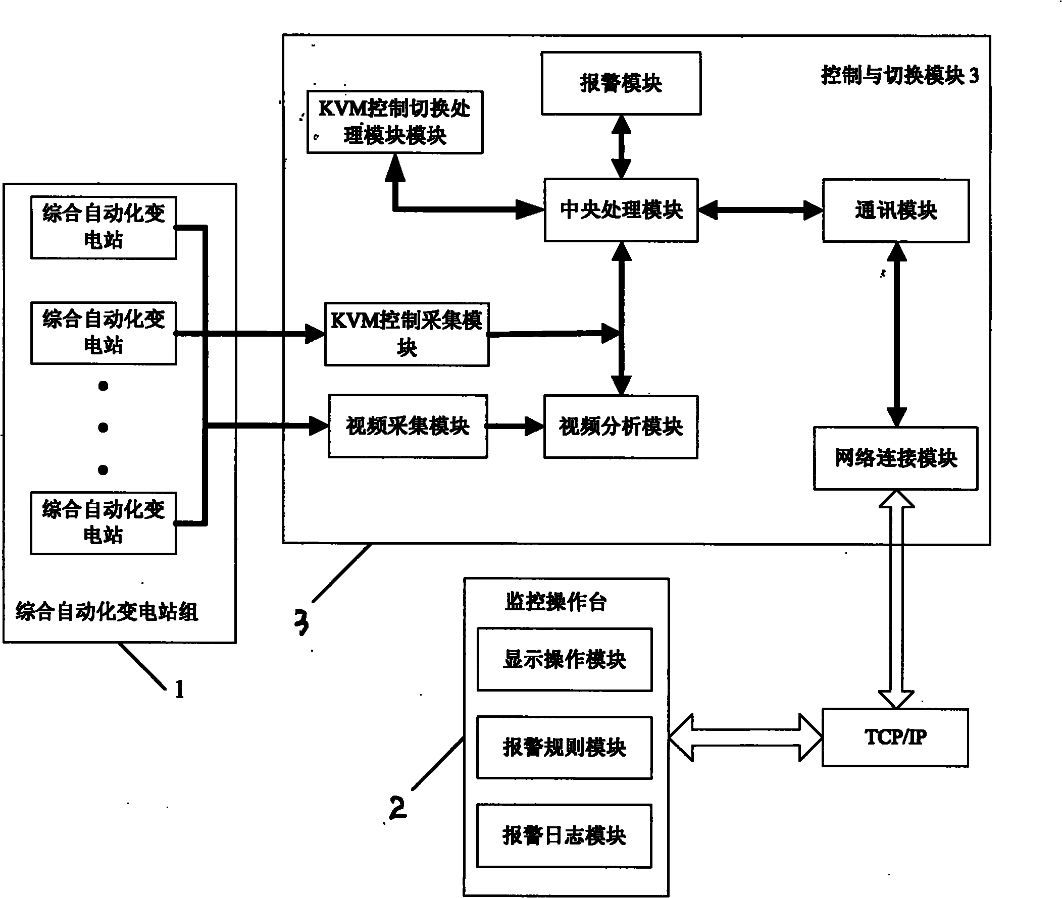
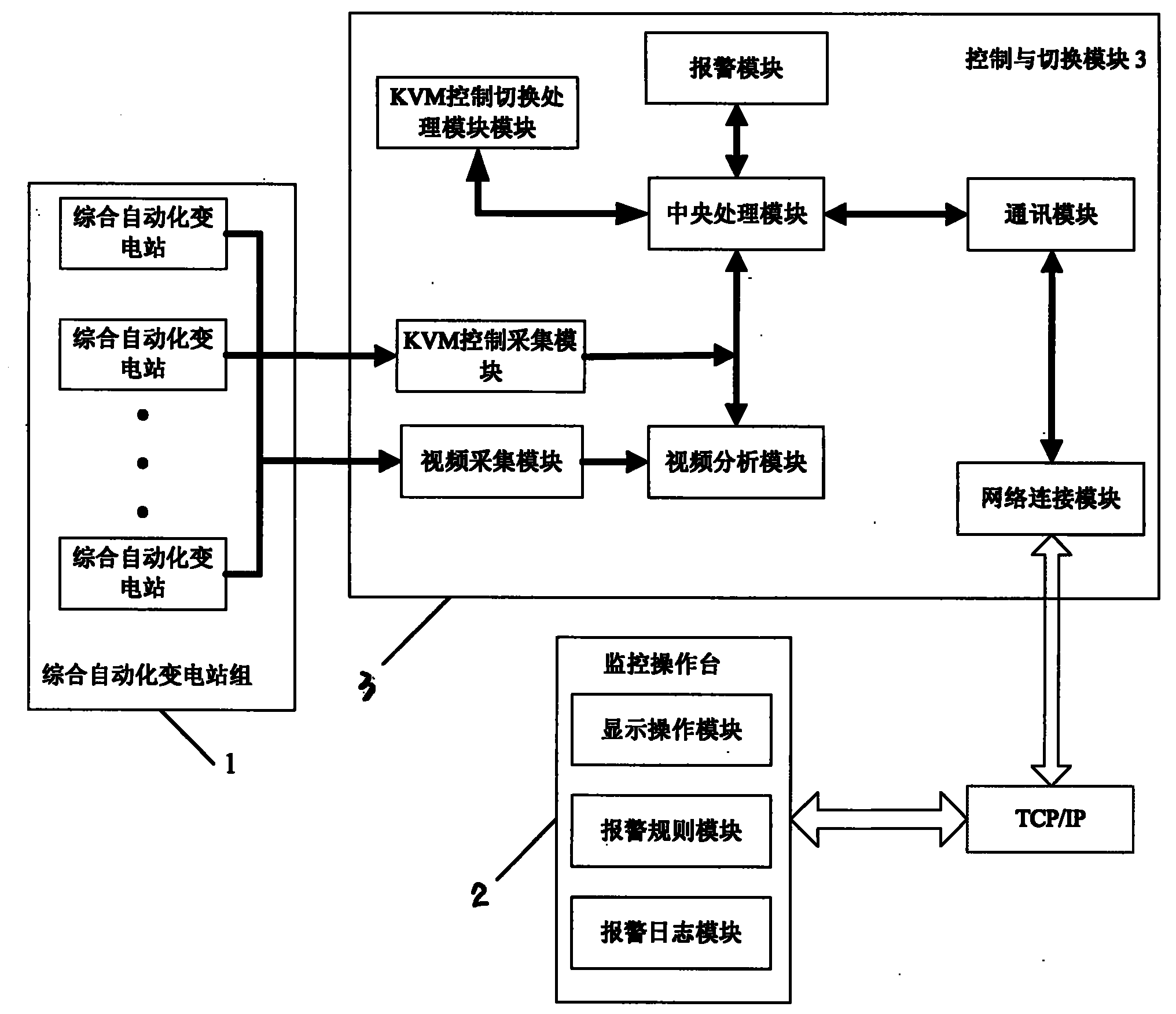
[0028] Such as figure 1 As shown, the present invention includes a comprehensive automated substation group 1 and a monitoring console 2, both of which are connected to a control and switching module 3.

[0029] The following will be explained respectively:

[0030] The integrated automation substation group 1 consists of at least one integrated automation substation. Generally speaking, an integrated automated substation group 1 includes sixteen integrated automated substations.

[0031] The control and switching module 3 includes a KVM control acquisition module and a video acquisition module, wherein the KVM control acquisition module acquires the operation control information of each integrated automation substation; the video acquisition module acquires the current picture information of each integrated automation substation, and converts the current picture information After conversion, it is sent to the video analysis module, and the video analysis module obtains the ...

Embodiment 2

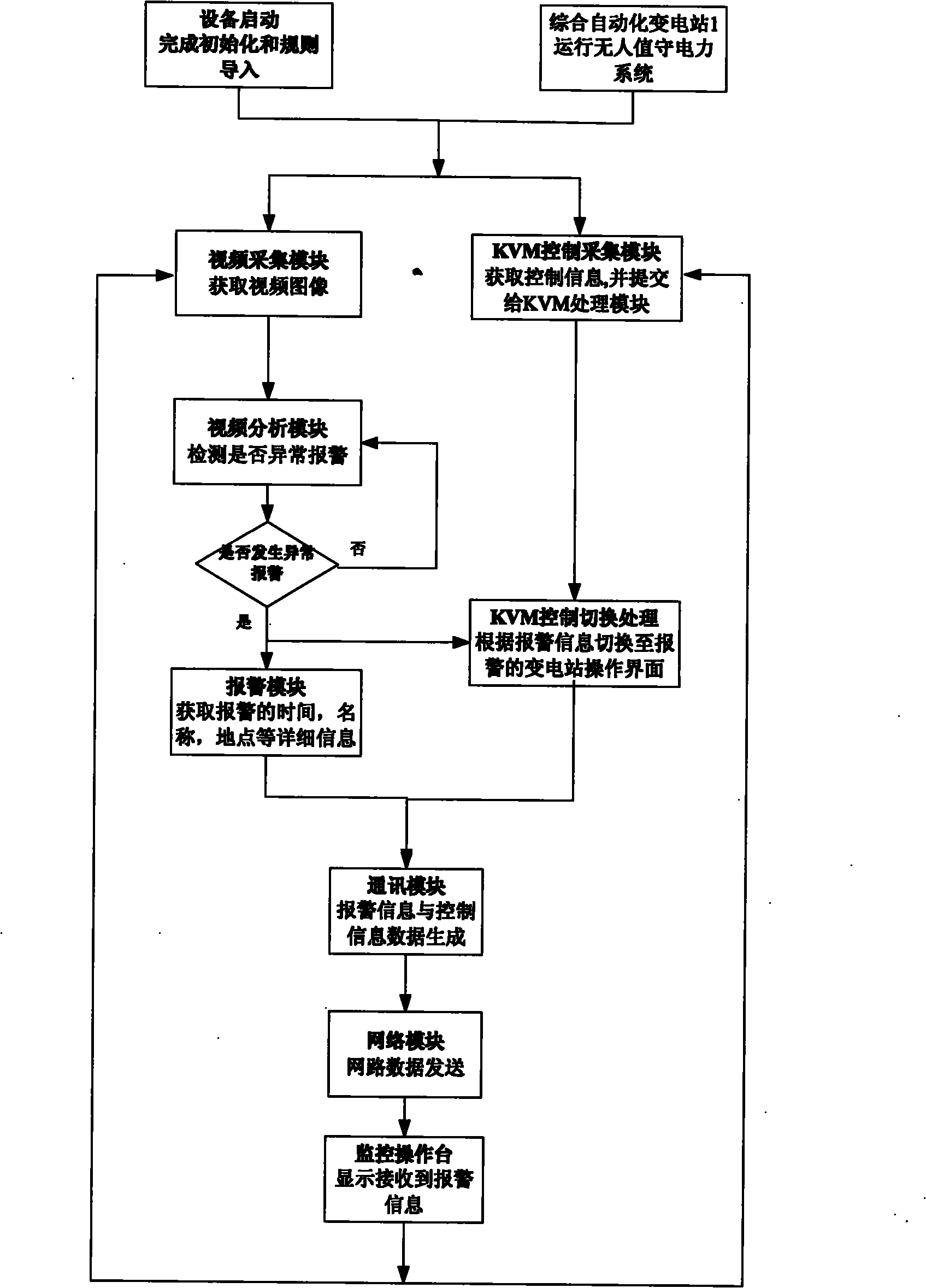
[0048] The difference between this embodiment and Embodiment 1 is that in this embodiment, the video analysis module obtains the video analysis result through the following steps:

[0049] Step 1, video preprocessing: preprocessing the acquired substation monitoring current picture information,

[0050] The above preprocessing includes removing noise, adjusting frame rate and frame size;

[0051] Step 2, background modeling: establish a reasonable and real background in order to obtain accurate foreground targets;

[0052] Step 3, target tracking: overcome the occlusion problem in target tracking, track multiple targets in the scene, and record their trajectory and direction;

[0053] Step 4, analysis of the movement trajectory: according to the movement trajectory of the target and the set alarm triggering rules, analyze whether the movement trajectory of the target belongs to abnormal activities, and if so, trigger an alarm;

[0054] Step five, target identification: ident...

Embodiment 3

[0057] The difference between this embodiment and the above-mentioned embodiments 1 and 2 is that it is set according to the characteristics of centralized control of multiple integrated automation substations in the centralized control station, that is, each integrated automation substation in the integrated automation substation group 1 is connected to a monitoring console 2-phase connection.

[0058] Generally, multiple integrated automated substations require multiple monitoring consoles, and 16 integrated automated substations require 16 monitoring consoles, and staff also need to monitor and maintain multiple operating consoles in real time. The system can set the specified time to start automatically taking turns to display the monitoring operation information of 16 integrated automatic substations on a monitoring console at the set time interval, so as to achieve the goal of saving costs and reducing the workload of maintenance personnel.


PUM


Abstract

The invention discloses a network-based multi-station monitoring integrated matrix display control system, which comprises a comprehensive automatic substation group and a monitoring operation platform, wherein the comprehensive automatic substation group and the monitoring operation platform are both connected with a control and switching module. The system has the advantages that: 1, a user canbe conveniently switched to any monitored remote substation for operations according to needs on control equipment without going to a field for maintenance per se; 2, monitored running images of a plurality of remote substations can be transmitted to a center control room to fulfill the aim of displaying the monitored running images of the plurality of substations on one piece of video display equipment for workers to view and browse; and 3, the system has automatic intelligent alarming switching capability because alarming rules are set, starts automatically displaying the image of an alarming substation after the alarming rules are triggered, and is switched to an alarming substation operating interface to discover abnormal substation running information in the first place.

Description

technical field [0001] The invention belongs to the technical field of digital image and communication, and in particular relates to a substation monitoring image acquisition analysis and switching system. Background technique [0002] At present, all monitoring and processing information systems of monitoring substations operate independently and independently. The existing problems are as follows: First, the access and debugging of the controlled station in the centralized control system is inconvenient. When a new centralized control station is established, it is necessary to Existing substations are added to the centralized control system as controlled stations. However, the lines of most substations are running, and the line cannot be debugged in the centralized control system. Only when the line is out of power or a special power outage plan is made, can it be debugged. This brings great inconvenience to the initial debugging work of the centralized control system. ...

Claims


Application Information

Patent Timeline
Patent Type & Authority Applications(China)
IPC IPC(8): H02J13/00G06T7/20G06K9/00
Inventor 王璐王春生丁东坡张喆郑彦新
Owner STATE GRID CORP OF CHINA
Why Eureka
Try Eureka