Lighting device having at least one heat sink

A technology for lighting devices and radiators, applied in lighting devices, cooling/heating devices of lighting devices, lighting and heating equipment, etc., can solve problems such as poor cooling effect, uneven temperature distribution, low flow rate, etc., and achieve compact structure, The effect of good protection and simple structure

Inactive Publication Date: 2012-02-01
OSRAM GMBH
View PDF4 Cites 2 Cited by
  • Summary
  • Abstract
  • Description
  • Claims
  • Application Information

AI Technical Summary

Problems solved by technology

[0004] Poor cooling due to higher pressure and low flow rate due to deflection of the cooling air flow
Furthermore, if the air flow is not guided exactly vertically onto the heat sink, for example due to a slightly inclined position of the fan relative to the heat sink, uneven cooling of the heat sink due to the uneven outflow of air can lead to uneven cooling. Desired non-uniform temperature distribution

Method used


Image

  • Lighting device having at least one heat sink
  • Lighting device having at least one heat sink
  • Lighting device having at least one heat sink

Examples


Embodiment Construction

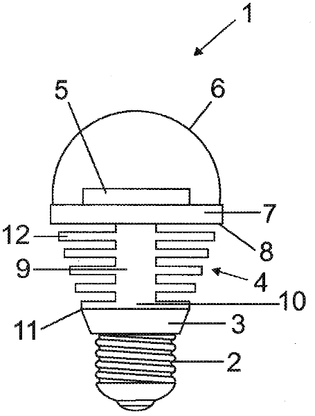
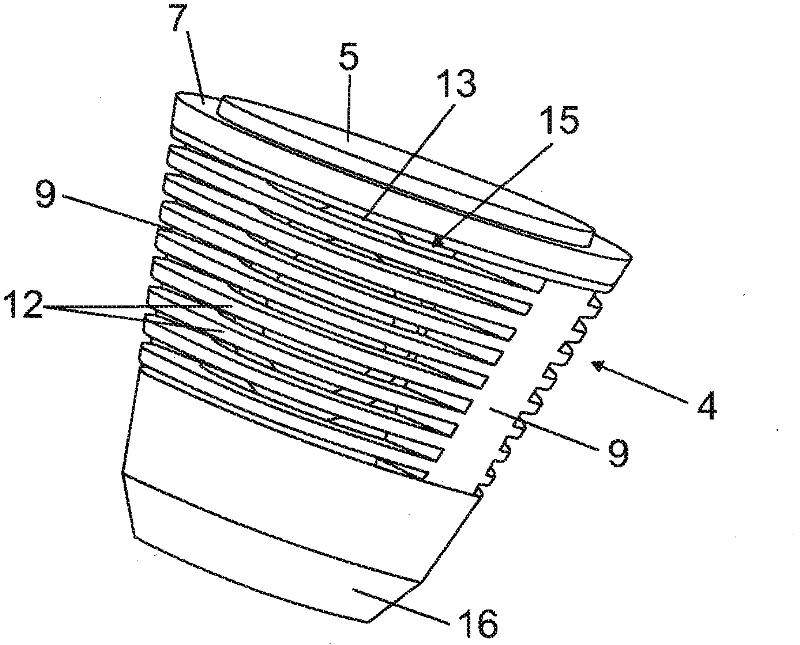
[0034] figure 1 A side sectional view of a so-called LED retrofit lamp 1 as a first embodiment of the lighting device 1 according to the invention is shown. The lamp 1 has a conventional screw base 2 (so-called Edison thread), a driver circuit 3, a heat sink 4, a light emitting diode (LED) 5 as light source 5, and a bulb 6 which protects the LED 5 from the surrounding environment. The outer contour of the retrofit lamp 1 mimics a conventional incandescent lamp. The LED 5 is placed on the flat base 7 of the first heat sink 4 and emits light in the upper half of the space. On the side 8 of the first base 7 facing away from the LED 5 , the heat sink 4 has two side webs 9 , of which only the front side web is visible here. In addition, on the end 10 of the side web 9 facing away from the first base 7 , a second base 11 is arranged non-parallel to the first base, which carries the drive circuit 3 and thus serves for the drive circuit 3 . cool down.

[0035] Cooling fins 12 are ...


PUM


Abstract

The invention relates to a lighting device (1) comprising at least one heat sink (4) and a base (7) for accommodating at least one light source (5) and at least one device (13) connected to the lighting device (1) for generating a cooling media flow, in particular an air flow. According to the invention, the cooling media flow runs predominantly parallel to the plane of the preferably at least approximately flat base (7) of the heat sink (4).

Description

technical field [0001] The invention relates to a lighting device with: at least one heat sink; a preferably at least approximately flat base for receiving at least one light source; and at least one cooling medium connected to the lighting device, in particular air flow device. Background technique [0002] Especially when lighting devices use light-emitting diodes (LEDs) to emit light, the lighting devices often require a cooling device by which the light sources can be cooled during operation so that they have a long service life and achieve the desired lighting quality. In addition, the cooling device has at least one preferably flat base, on which the LEDs are mounted directly or on a suitable carrier. [0003] At higher power levels, passive heat sinks are no longer sufficient to ensure the desired cooling effect, and devices for generating a cooling medium flow which improves the dissipation of thermal power by convection are generally used. For this purpose, in the...

Claims


Application Information

Patent Timeline
Patent Type & Authority Applications(China)
IPC IPC(8): F21V29/02F21K99/00
CPCF21K9/135F21V29/02F21Y2101/02F21V29/677F21V29/745F21V29/75F21V29/76F21V29/77F21V29/83F21K9/232F21Y2115/10F21V29/60F21V29/74F21V29/80
Inventor 妮科尔·布赖德纳塞尔
Owner OSRAM GMBH
Why Eureka
Try Eureka