Microprocessor controlled expiratory valve

A microcomputer control and exhalation valve technology, applied in the field of microcomputer control exhalation valve, stepless adjustment of end-expiratory pressure devices, can solve the problems of low control accuracy and inability to feedback closed-loop control, etc.

Inactive Publication Date: 2012-02-08
BEIJING AEROSPACE CHANGFENG CO LTD
View PDF0 Cites 4 Cited by
  • Summary
  • Abstract
  • Description
  • Claims
  • Application Information

AI Technical Summary

Problems solved by technology

Most of the current technologies use mechanical control, which is adjusted by adjusting the pressure of the spr

Method used


Image

  • Microprocessor controlled expiratory valve
  • Microprocessor controlled expiratory valve
  • Microprocessor controlled expiratory valve

Examples


Embodiment Construction

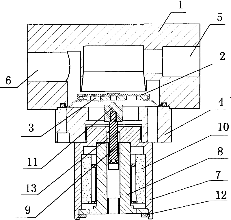
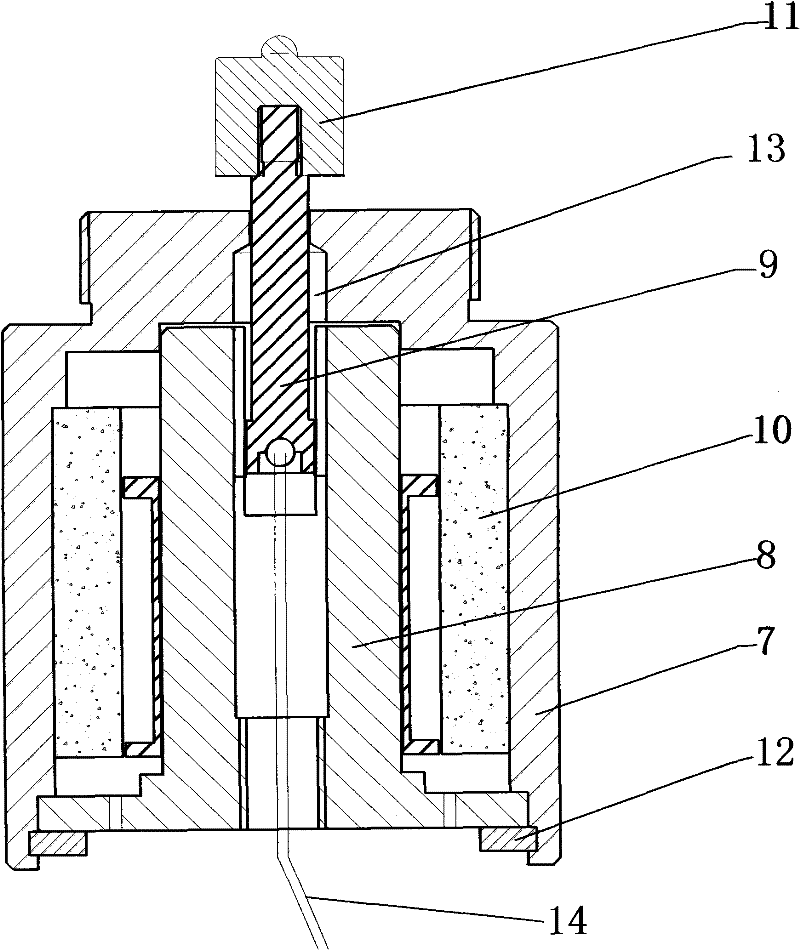
[0012] figure 1 Among them, the microcomputer-controlled exhalation valve provided by the present invention includes a valve body 1, a diaphragm 2, a pressure sheet 3, and a gland 4. The valve body 1 is provided with an air inlet 5 and an air outlet 6, and gas enters the valve through the air inlet 5. The body 1 is discharged from the air outlet 6 through the channel above the diaphragm 2. The microcomputer-controlled exhalation valve also includes a pressure controller. The pressure controller includes an outer yoke 7, an inner yoke 8, a coil 9, a magnet 10, a pressure head 11 and a collar 12, wherein the inner yoke 8 is located inside the outer yoke 7. , the magnet 10 is located between the outer yoke 7 and the inner yoke 8, the shape of the magnet 10 is tile-shaped, the magnetization direction is the radial direction, from N pole to S pole, and several magnets are evenly distributed in the inner cavity of the outer yoke . The inner yoke 8 is provided with a radial guide g...


PUM


Abstract

The invention discloses a microprocessor controlled expiratory valve, which comprises a valve body, a diaphragm, a pressing plate, a gland and a pressure controller, wherein the pressure controller comprises an outer magnetic yoke, an inner magnetic yoke, a coil, a plurality of magnets, a pressing head and a clamping ring; the inner magnetic yoke is positioned in the outer magnetic yoke; the magnets are positioned between the outer magnetic yoke and the inner magnetic yoke and are tile-shaped, and the magnetization direction is radial and faces an N pole on one side and faces an S pole on the other side; the magnets are uniformly distributed in an inner cavity of the outer magnetic yoke; the inner magnetic yoke is provided with a radial guide groove; one end of the coil is positioned in the guide groove, and the other end is provided with the pressing head; the clamping ring is positioned at the bottom of the outer magnetic yoke; and the outer magnetic yoke is provided with threads which are connected with the gland of the expiratory valve. A wire of the coil is connected with a microprocessor control circuit, and on and off of input current and amplitude of the current are controlled by a microprocessor, so that end-expiratory pressure of a patient can be accurately controlled.

Description

technical field [0001] The invention relates to a microcomputer-controlled exhalation valve, a device capable of steplessly adjusting the end-expiratory pressure, which is mostly used in anesthesia machines, electric-electrically-controlled ventilators and pneumatic-electrically-controlled ventilators, and belongs to the technical field of medical equipment manufacturing. Background technique [0002] The ventilator is mainly used clinically to treat patients with respiratory failure, and the anesthesia machine is mainly used for patients who need general anesthesia surgery. During the operation and treatment process, the precise adjustment of the patient's end-expiratory pressure according to the patient's condition has therapeutic significance for the patient. major. Most of the current technologies use mechanical control, which is adjusted by adjusting the pressure of the spring. The disadvantage is that the control accuracy is low and feedback cannot be used for closed-l...

Claims


Application Information

Patent Timeline
IPC IPC(8): A61M16/20
Inventor 梁晨杨慧民闫全国刁俊李芳
Owner BEIJING AEROSPACE CHANGFENG CO LTD
Why Eureka
Try Eureka