Steel circle spring brake block device
A technology of brakes and steel circles, applied in the direction of brake parts, brake types, brake components, etc., can solve the problems of easy sparks, easy damage of brake discs, and high braking noise of vehicles, and achieves weight reduction, Manufacturing-friendly effects
- Summary
- Abstract
- Description
- Claims
- Application Information
AI Technical Summary
Problems solved by technology
Method used
Image

Examples
Embodiment 1
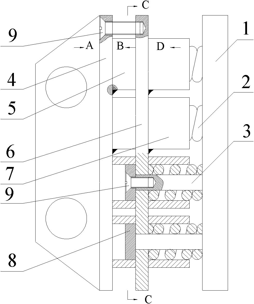
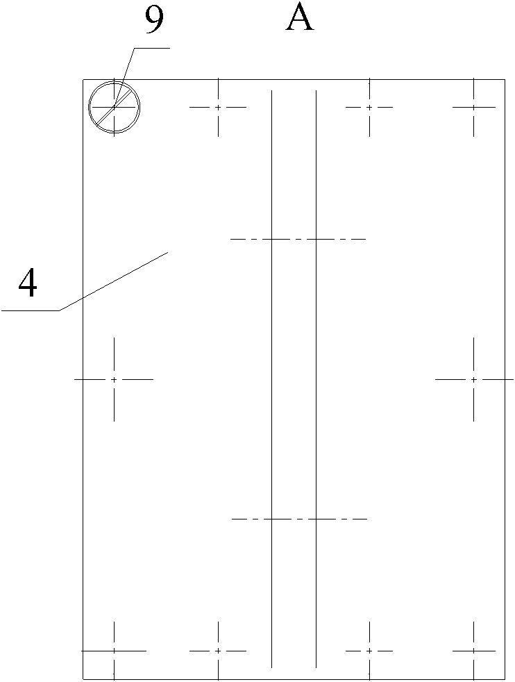
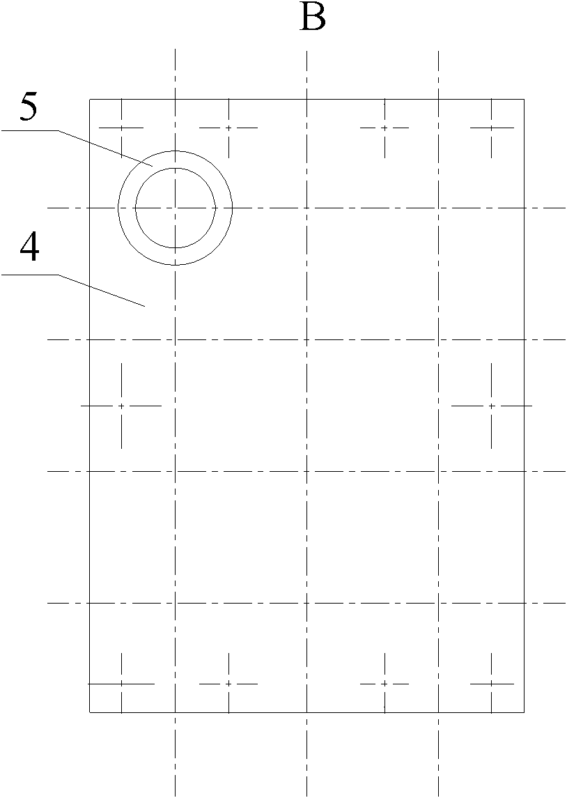
[0021] A steel round spring brake shoe device, the maximum elastic deformation is 10mm, the structure of the brake shoe device is as follows figure 1 As shown, it is composed of friction part 1, spring 2, sliding shaft 3, two steel plates, two sets of hollow steel pipes and disc slider 8, the length of sliding shaft 3 is 30mm, and is fixedly connected with friction part 1, and spring 2 is set On the sliding shaft 3, the spring 2 is a helical circular spring with a length of 30mm and a stiffness of 1.65MN / m along the axial direction. The end of the sliding shaft 2 is connected to the disc slider 8 through a countersunk screw 9, as Figure 4 shown. The sliding shaft 3 and the spring 2 are arranged in the first group of hollow steel pipes 5. There is a gap of 5 mm between the group of hollow steel pipes and the friction parts 1. The second group of hollow steel pipes 7 is provided with a disc slider 8. The first group The hollow steel pipes 5 and the second group of hollow steel...
Embodiment 2
[0025] A steel round spring brake shoe device, the maximum elastic deformation is 10mm, the brake shoe device includes friction parts, sliding shaft, spring, two steel plates, two sets of hollow steel pipes and disc sliders, the length of the sliding shaft is 20mm, fixedly connected with the friction parts, the spring is set on the sliding shaft, the spring is a helical round spring, the length is 30mm, the stiffness along the axis is 1.65MN / m, the end of the sliding shaft slides with the disc through the countersunk head screw block connection, the sliding shaft and the spring are set in the first group of hollow steel pipes, there is a gap of 4mm between the group of hollow steel pipes and the friction parts, the second group of hollow steel pipes is equipped with disc sliders, the first group and the second A set of hollow steel pipes is correspondingly welded to both sides of the first steel plate, and a screw hole is opened on the first steel plate, and a countersunk screw...
Embodiment 3
[0027] A steel round spring brake shoe device, the maximum elastic deformation is 10mm, the brake shoe device includes friction parts, sliding shaft, spring, two steel plates, two sets of hollow steel pipes and disc sliders, the length of the sliding shaft is 40mm, fixedly connected with the friction parts, the spring is set on the sliding shaft, the spring is a helical round spring, the length is 30mm, the stiffness along the axis is 1.65MN / m, the end of the sliding shaft slides with the disc through the countersunk head screw block connection, the sliding shaft and spring are set in the first group of hollow steel pipes, there is a gap of 6mm between the group of hollow steel pipes and the friction parts, the second group of hollow steel pipes is equipped with disc sliders, the first group and the second A set of hollow steel pipes is correspondingly welded to both sides of the first steel plate, and a screw hole is opened on the first steel plate, and a countersunk screw con...
PUM
 Abstract
Description
Claims
Application Information
 - R&D
- Intellectual Property
- Life Sciences
- Materials
- Tech Scout
- Unparalleled Data Quality
- Higher Quality Content
- 60% Fewer Hallucinations
Browse by: Latest US Patents, China's latest patents, Technical Efficacy Thesaurus, Application Domain, Technology Topic, Popular Technical Reports.
© 2025 PatSnap. All rights reserved.Legal|Privacy policy|Modern Slavery Act Transparency Statement|Sitemap|About US| Contact US: help@patsnap.com