Cage-type spring

A technology of cage springs and spring groups, which is applied to springs, springs/shock absorbers, spring components composed of several springs, etc., can solve problems such as high requirements for production equipment, cumbersome production processes, and increased production costs, and achieve Small size, stable compression state, uniform force effect

Inactive Publication Date: 2012-02-08
贺智挺
View PDF4 Cites 22 Cited by
  • Summary
  • Abstract
  • Description
  • Claims
  • Application Information

AI Technical Summary

Problems solved by technology

These materials are expensive, the production process is cumbersome, and the requirements for production equipment are high, which greatly increases its production cost.

Method used


Image

  • Cage-type spring
  • Cage-type spring
  • Cage-type spring

Examples


Embodiment 1

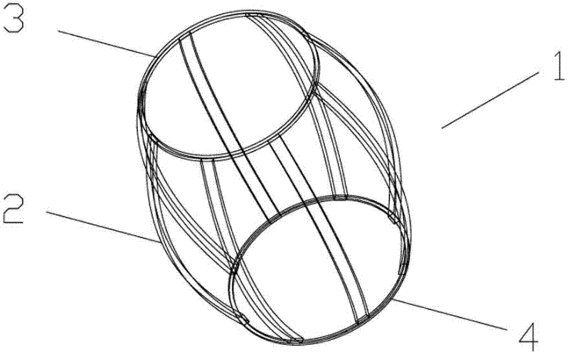
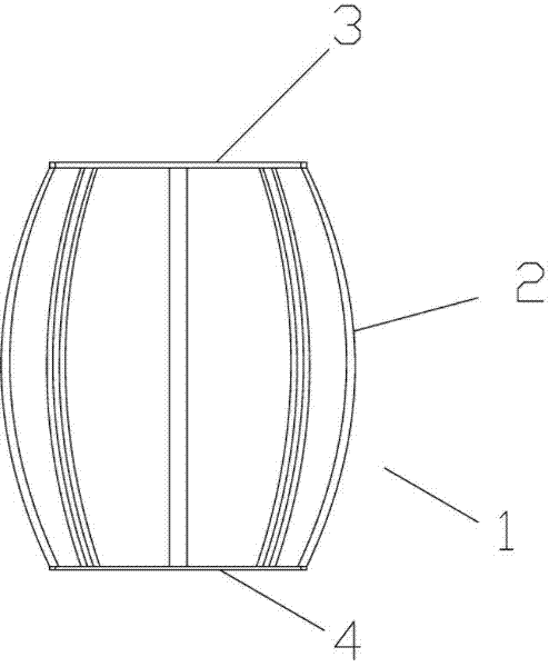
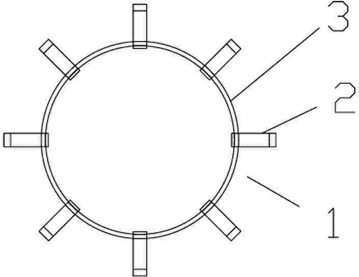
[0022] Embodiment one: refer to Figure 1 to Figure 3 , a cage spring provided by the present invention is simple in structure, small in size, high in bearing capacity, and low in production cost. The cage spring is composed of a section of spring group 1, which includes eight The shrapnel 2, the eight shrapnels 2 are evenly distributed around the center line, so that the force is more balanced, the two ends of the shrapnel 2 are respectively fixed on the upper and lower connecting rings 3, 4, and the shrapnel 2 is bent outward toward the center line . The cage spring in this example is composed of a section of spring group 1. When the spring is under pressure, the shrapnel 2 bends outward under the action of the pressure, and the pressure is shared by eight shrapnel 2. Compared with the traditional single spring coil spring, When the same material is used and the diameter of the spring wire is equal to the diameter of the shrapnel 2, the load that this embodiment can bear is...

Embodiment 2

[0023] Embodiment two: refer to Figure 4 , Figure 5 , the structure and principle of this embodiment are basically the same as those of Embodiment 1, the difference lies in: the elastic piece 2 is bent inward toward the center line. That is, when the spring is under pressure, the shrapnel 2 bends inward under the action of the pressure, thereby reducing the volume of the deformed spring and making it more widely used.

Embodiment 3

[0024] Embodiment three: refer to Figure 6 , Figure 7 , the structure and principle of this embodiment are basically the same as that of Embodiment 1, the difference is that: when the upper connecting ring 3 or the lower connecting ring 4 is small enough or infinitely small, the ends of all the shrapnel 2 are directly connected together, that is One or both ends of the spring are conical to form a conical spring.

[0025] Embodiment three: refer to Figure 8 , Figure 9 , the structure and principle of this embodiment are basically the same as that of Embodiment 1, the difference is that in this embodiment, the cage spring is composed of four spring groups 1, and each spring group 1 is arranged from top to bottom along the center line . Of course, here, the center line can be not only a straight line, but also a spatial curve, which has the same technical effect and is an equivalent technical solution.

[0026] According to the present invention, the volume, bearing cap...


PUM


Abstract

The novel invention discloses a cage-type spring which has the advantages of simple structure, small volume, high carrying capacity and low manufacturing cost. The cage-type spring is composed of one or multiple sections of spring groups, wherein each spring group comprises multiple elastic sheets which are arranged surrounding a centre line; and the two ends of each elastic sheet are respectively fixed on an upper connecting ring and a low connecting ring, and the elastic sheets are bent inward or outward relative to the centre line. The spring provided by the invention is composed of one or multiple sections of spring groups, and each spring group is composed of the multiple elastic sheets which surround the centre line and are in cage-shaped arrangement, when the spring is subjected to the pressure, the elastic sheets are bent inwards or outwards under the action of pressure, the multiple elastic sheets share the pressure together and are uniformly stressed, and the compaction state is stable. Compared with the traditional single spring wire spiral spring, the cage-type spring provided by the invention has the following advantages: under the conditions that the cage-type spring is made of a same material and the diameter of a spring wire is equal to that of each elastic sheet, the load born by the cage-type spring composed of eight elastic sheets is eight times that of the spiral spring, the volume of the cage-type spring is smaller and the cage-type spring is more simple and more convenient in use.

Description

technical field [0001] The invention relates to a spring. Background technique [0002] Spring is a mechanical part that uses elasticity to work. It is used to control the movement of parts, alleviate shock or vibration, store energy, measure force, etc. It is widely used in machines and instruments. The types of springs are complex and diverse. According to the nature of the force, springs can be divided into tension springs, compression springs, torsion springs and bending springs. Among them, the most commonly used compression spring is a helical spring that bears downward pressure. The cross-section of the material it uses is mostly circular, and it is also made of rectangular and multi-strand steel coils. The shapes are: cylindrical, conical, convex and concave, and a small amount of non-circular, etc. There is a certain gap between the rings of the compression spring. When the spring is subjected to an external load, the spring shrinks and deforms to store deformation...

Claims


Application Information

Patent Timeline
Patent Type & Authority Applications(China)
IPC IPC(8): F16F3/087F16F1/373F16F1/366
Inventor 贺智挺
Owner 贺智挺
Why Eureka
Try Eureka