Device for spray lubricating wind turbine transmission

A wind turbine and transmission technology, which is applied in the directions of engine lubrication, transmission parts, turbines, etc., can solve problems such as increasing the risk of transmission failure, and achieve simple cost and good wetting effect.

Inactive Publication Date: 2012-02-08
SIEMENS AG
View PDF0 Cites 5 Cited by
  • Summary
  • Abstract
  • Description
  • Claims
  • Application Information

AI Technical Summary

Problems solved by technology

This increases the risk of transmission failure

Method used


Image

  • Device for spray lubricating wind turbine transmission
  • Device for spray lubricating wind turbine transmission

Examples


Embodiment Construction

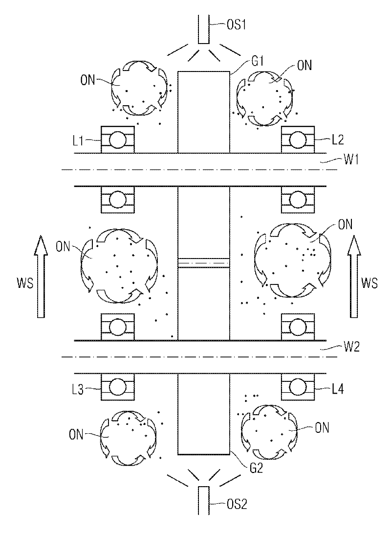
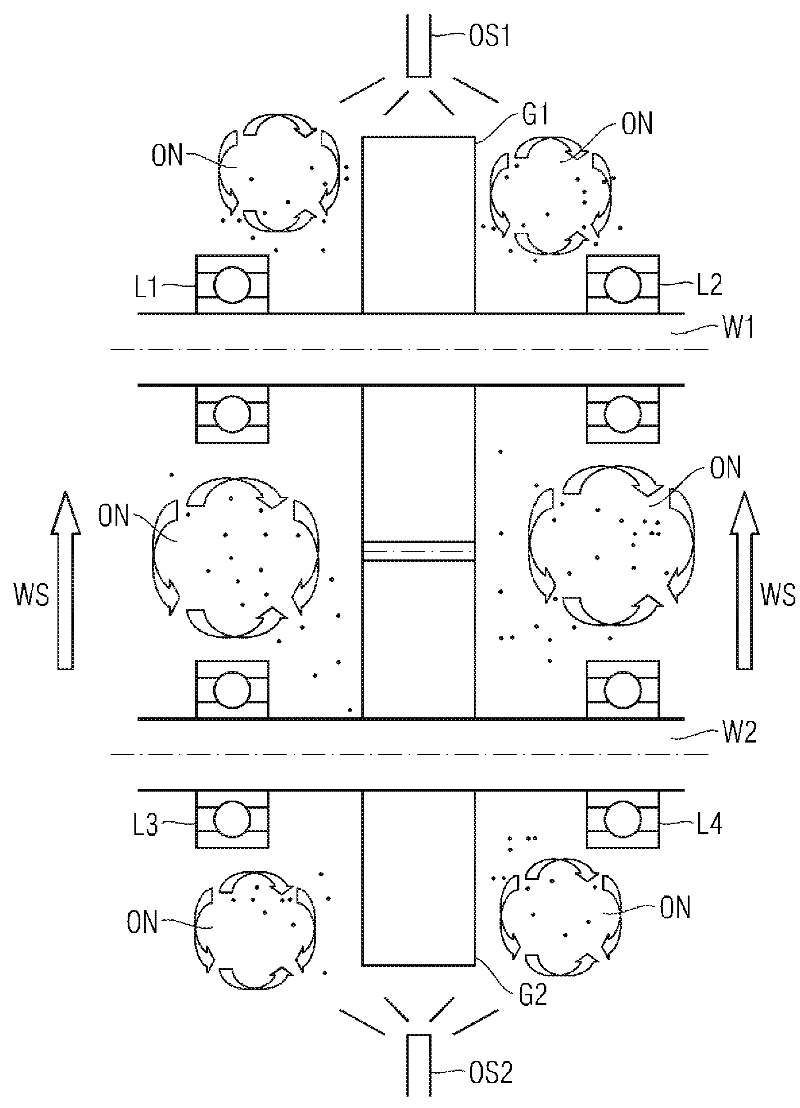
[0015] The device according to the invention comprises a transmission, which in figure 1 is represented schematically by two spur gears G1 , G2 , two transmission shafts W1 , W2 and four bearings L1 , L2 , L3 , L4 . The gears G1 , G2 , W1 , W2 , L1 , L2 , L3 , L4 are surrounded by a gear housing (not shown).

[0016] The device according to the invention also includes two fuel injection devices OS1 , OS2 which together form a fuel injection system. The oil spray devices OS1 , OS2 are arranged spatially separated from one another on the transmission housing and nonetheless at least their spray heads are located inside the housing. In a preferred embodiment, the oil injection devices OS1 , OS2 are mounted on the inner side of the transmission housing.

[0017] except two in figure 1 In addition to the fuel injection devices OS1 and OS2 shown in the middle part, other fuel injection devices may also belong to the fuel injection system.

[0018] The two oil injection devices O...


PUM


Abstract

A device for spray lubrication of a wind turbine transmission is provided. The device includes a transmission enclosed by a housing, a first oil spray unit and a second oil spray unit. Both of the oil spray units are arranged in the interior of the housing. The first oil spray unit is embodied to spray oil at a first temperature in the interior of the transmission housing, while the second oil spray unit is embodied to spray oil at a second temperature in the interior of the transmission housing, wherein the first and the second temperature differ from each other.

Description

technical field [0001] The present invention relates to devices and methods for spray lubrication of wind turbine transmissions. Background technique [0002] In order to keep the wear of the transmission as low as possible, it is necessary that the individual transmission elements, for example the teeth of two spur gears meshing with each other, have no direct metal-to-metal contact. For this reason, it is important to consider sufficient lubrication so that all metal surfaces are wetted by an oil or lubricating film. [0003] However, during the start-up phase of the wind turbine drive or after a longer shutdown period, there is the risk that the film is not sufficiently applied to all metal surfaces. Due to the absence of a lubricating film, direct metal-to-metal contact can occur, which leads to increased friction and wear of the associated transmission components, for example in the form of chatter marks. This increases the risk of transmission failure. [0004] To s...

Claims


Application Information

Patent Timeline
Patent Type & Authority Applications(China)
IPC IPC(8): F16H57/04F16N39/04F03D11/00
CPCF16H57/046F16N7/32F01D9/065F16N2210/12F16N2210/025F03D11/0008Y02E10/722F16H57/0495F03D80/70Y02E10/72
Inventor M.布拉瑟尔C.阮
Owner SIEMENS AG
Why Eureka
Try Eureka