
Novel refrigeration system with energy system optimization device

A system optimization and refrigeration system technology, applied in refrigerators, refrigeration components, refrigeration and liquefaction, etc., can solve the problems of high liquid refrigerant temperature, low subcooling degree, and quality to be improved, so as to achieve the optimization and improvement of air conditioning energy system Quality and longevity, the effect of low production cost

Inactive Publication Date: 2012-02-08
佛山市众越节能环保技术开发有限公司 +1
View PDF6 Cites 8 Cited by
  • Summary
  • Abstract
  • Description
  • Claims
  • Application Information

AI Technical Summary

Problems solved by technology

[0003] At present, the common problem in the refrigeration system is that the gas at the inlet of the condenser is unsaturated high-temperature gas, and some of the gas is still not condensed into liquid after passing through the condenser. Because the density of the gas is much smaller than that of the liquid, the cooling of the condenser is reduced. Effect
This also leads to the high temperature of the liquid refrigerant flowing out of the condenser and the small subcooling degree, so it is easy to vaporize before throttling (that is, before the expansion valve or capillary tube), absorbing the heat outside, and reducing the cooling effect of the evaporator
[0004] On the other hand, the temperature of the gaseous refrigerant flowing out of the evaporator is low, the degree of superheat is small, and the gas contains a certain amount of liquid. Because the liquid is incompressible in the compressor, vibration occurs, that is, a hydraulic phenomenon, which reduces the quality and life of the refrigeration system.
Therefore, the energy utilization of the refrigeration system in the prior art is not ideal enough, and the quality needs to be improved.

Method used


Image

  • Novel refrigeration system with energy system optimization device
  • Novel refrigeration system with energy system optimization device
  • Novel refrigeration system with energy system optimization device

Examples


Embodiment Construction

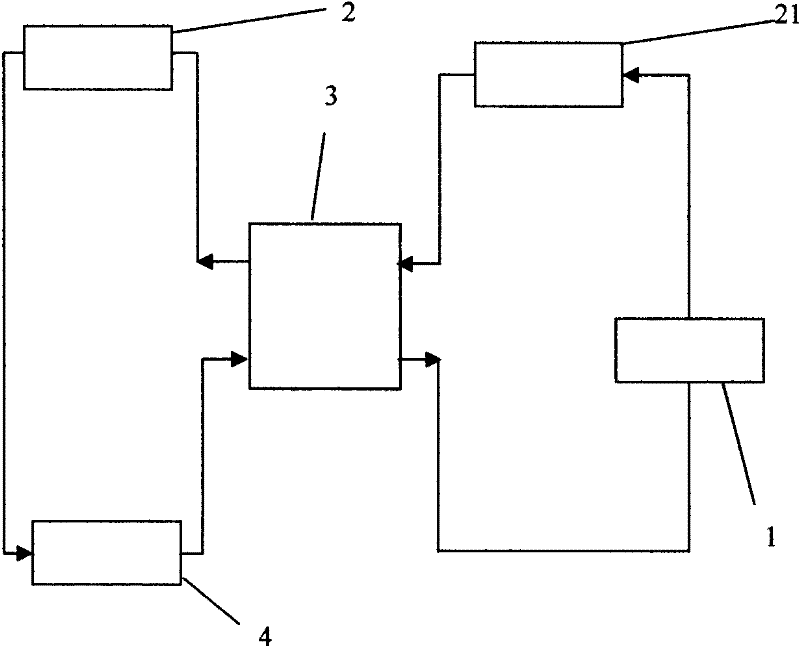
[0015] When retrofitting the existing refrigeration system, an energy system optimization device 3 is added to the traditional refrigeration system circuit. A transmission channel of the energy system optimization device 3 is connected to the condenser 2 or condenser 21 through a refrigerant pipeline, and the energy system Another transmission channel of the optimization device 3 is connected to the outlet of the evaporator 4 through a refrigerant pipeline.

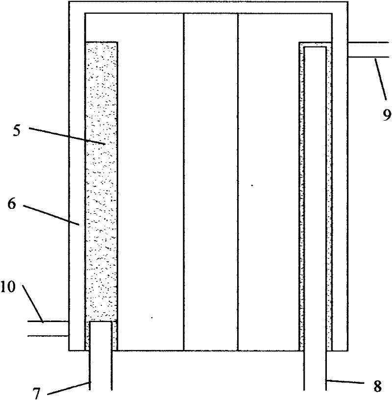
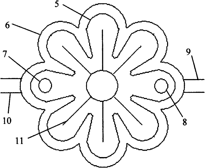
[0016] The gas inlet conduit 7 connected to the evaporator extends into the bottom of the inner layer 5 of the energy system optimization device, the gas outlet conduit 8 is at the top of the inner layer 5 of the energy system optimization device, and the inlet conduit 9 connected to the condenser is located at the outer layer of the energy system optimization device 6, while the liquid outlet conduit 10 is at the top of the outer layer 6 of the energy system optimization device. The purpose of the above approach is to le...


PUM


Abstract

The invention discloses a novel refrigeration system with an energy system optimization device. The refrigeration system is mainly characterized in that: the energy system optimization device is arranged in the conventional refrigeration system loop consisting of a compressor, a condenser and an evaporator. The energy system optimization device is connected with the condenser and the evaporator and can realize the heat exchange of low-temperature gas flowing out of the evaporator and high-temperature gas flowing into the condenser or high-temperature liquid flowing out of the condenser to improve the degree of supercooling of a refrigerant and achieve the effect of optimizing the efficiency of an air conditioning. Meanwhile, the energy system optimization device heats the gas, separates the liquid from the gas, makes the liquid reserved in the energy system optimization device until the liquid is completely heated and vaporized, prevents the liquid from flowing into the compressor, reduces the vibration and noise of the compressor, and effectively improves the operating efficiency of the compressor. Thus, the novel refrigeration system has the advantages of lowering energy consumption, improving the quality and service life of the refrigeration system and stably operating.

Description

Technical field: [0001] The invention relates to an energy-saving device for a refrigeration system, which belongs to the technical field of refrigeration. Background technique: [0002] High efficiency and energy saving is a strategic policy vigorously promoted by the country for a long time. Air-conditioning is widely used and brings great convenience to production and life, but the power consumption of air-conditioning is huge. Therefore, the energy-saving methods of air-conditioning and refrigeration systems are analyzed, and the design or existing systems are modified to reduce Energy consumption and reducing the negative impact on the environment is very meaningful. [0003] At present, the common problem in the refrigeration system is that the gas at the inlet of the condenser is unsaturated high-temperature gas, and some of the gas is still not condensed into liquid after passing through the condenser. Because the density of the gas is much smaller than that of the ...

Claims


Application Information

Patent Timeline
IPC IPC(8): F25B1/00F25B40/06
Inventor 赖朝安葛舜龙
Owner 佛山市众越节能环保技术开发有限公司
Learn More