Method for operating a hydraulic or pneumatic system

A pneumatic system and hydraulic technology, applied in the direction of hydraulic brakes, pump/compressor arrangement, brakes, etc., can solve problems such as inability to detect pressure, failure to detect faults, and small accumulator pressure

Inactive Publication Date: 2012-02-08
VOITH PATENT GMBH
View PDF2 Cites 7 Cited by
  • Summary
  • Abstract
  • Description
  • Claims
  • Application Information

AI Technical Summary

Problems solved by technology

If this is the case, the increased pressure of the valve device as regulating valve cannot be detected by the subsequent pressure regulating object
Then the difficulty of adjustment is increased accordingly, because the inlet pressure of the system is not known
Furthermore, without such a pressure sensor in the area of ​​the pressure accumulator, it is not possible to determine whether the insufficient pressure in the area behind the valve arrangeme

Method used


Image

  • Method for operating a hydraulic or pneumatic system
  • Method for operating a hydraulic or pneumatic system
  • Method for operating a hydraulic or pneumatic system

Examples


Example Embodiment

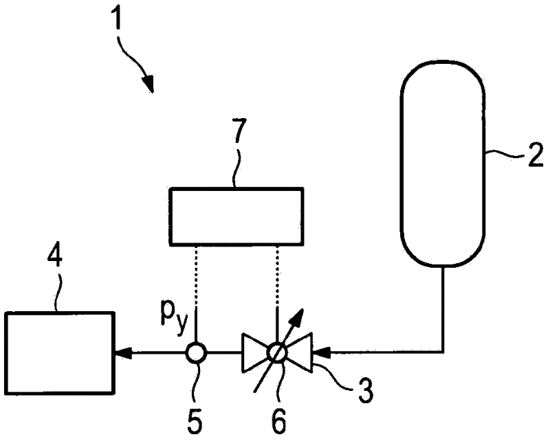
[0025] figure 1 A pneumatic or hydraulic system 1 is shown schematically in the middle height. Insofar as the present invention should not therefore be limited to pneumatic systems, the following figure 1 The system exemplified in is described as a pneumatic system 1 , wherein the construction according to the invention can be applied in a correspondingly analogous manner to a hydraulic system by any person skilled in the art.

[0026] figure 1The pneumatic system basically consists of a pressure accumulator 2 , a valve device 3 and a pneumatic application system 4 , wherein the desired process is carried out by means of the pressure controllably or regulated by the valve device 3 . An example of such a process in the application system 4 is the control of the corresponding valves, which control, for example, the braking system of a commercial vehicle. In the application system 4 , it is therefore possible to provide, in particular, the design of pneumatic valve arrangement...


PUM


Abstract

The invention relates to a method for operating a hydraulic or pneumatic system. The system comprises at least one pressure accumulator. The system is provided with at least one valve unit and a sensor for the at least indirect detection of the position of the valve unit and/or at least one sensor for the detection of a value that is at least indirectly related to the pressure on the side of the valve unit facing away from the pressure accumulator. At least one value is detected with one of the sensors when using the method. According to the invention, the detected value or values is or are compared to reference values. On the basis of an agreement or a difference between the value(s) and the reference values, an error function of the system and/or the pressure in the region of the system present on the side facing away from the sensor for detecting a value which relates at least indirectly to the pressure on the side of the valve unit facing away from the pressure accumulator, are determined.

Description

technical field [0001] The invention relates to a method for operating a hydraulic or pneumatic system having the features defined in claims 1 and 8 in the preamble. Background technique [0002] Pneumatic and / or hydraulic systems with storage devices and corresponding valves are known from the general prior art. In addition, systems of this type often have sensors and / or devices which make it possible to detect the pressure in the system and / or the position of the state of the valve device. An example of such a system here is a compressed air system or a compressed air supply system of a motor vehicle. Such a system is known, for example, from DE 10 2004 059 835 A1. [0003] In this case, it is typical for such compressed air systems that they have a pressure accumulator which, depending on the driving state, is supplied with an inlet pressure by the compressor accordingly. In this case, the pressure sensor is often arranged on the side of the valve arrangement relevant ...

Claims


Application Information

Patent Timeline
IPC IPC(8): B60T17/02G01L27/00B60T10/02
CPCB60T10/02B60T17/221
Inventor 安德烈亚斯-尼古拉斯·迈尔于尔根·贝茨米尔科·维瑟曼马库斯·比朔夫罗兰·舍雷尔
Owner VOITH PATENT GMBH
Why Eureka
Try Eureka