Environment-friendly method for filling liquid nitrogen and liquid argon

An environmentally friendly filling technology, applied in container filling methods, equipment loaded into pressure vessels, gas/liquid distribution and storage, etc., can solve problems such as waste, customer economic loss, noise pollution, etc., to avoid waste, solve Noise pollution and waste, easy operation effect

Inactive Publication Date: 2012-02-15
苏庆魁
View PDF5 Cites 4 Cited by
  • Summary
  • Abstract
  • Description
  • Claims
  • Application Information

AI Technical Summary

Problems solved by technology

[0006] 1. Noise pollution: when the storage tank discharge valve 4 releases nitrogen gas, it produces a piercing squeaking sound, which forms a source of noise pollution
[0007] 2. During the filling process, the discharge valve of the storage tank is always open and discharged, resulting in a lot of waste. The longer the filling time, the more waste; the more liquid nitrogen or liquid argon the customer needs, the more waste will be. Cause a lot of economic loss, that is to say, the waste of this filling method is proportional to the filling time and the amount required by customers

Method used


Image

  • Environment-friendly method for filling liquid nitrogen and liquid argon
  • Environment-friendly method for filling liquid nitrogen and liquid argon

Examples


Embodiment 1

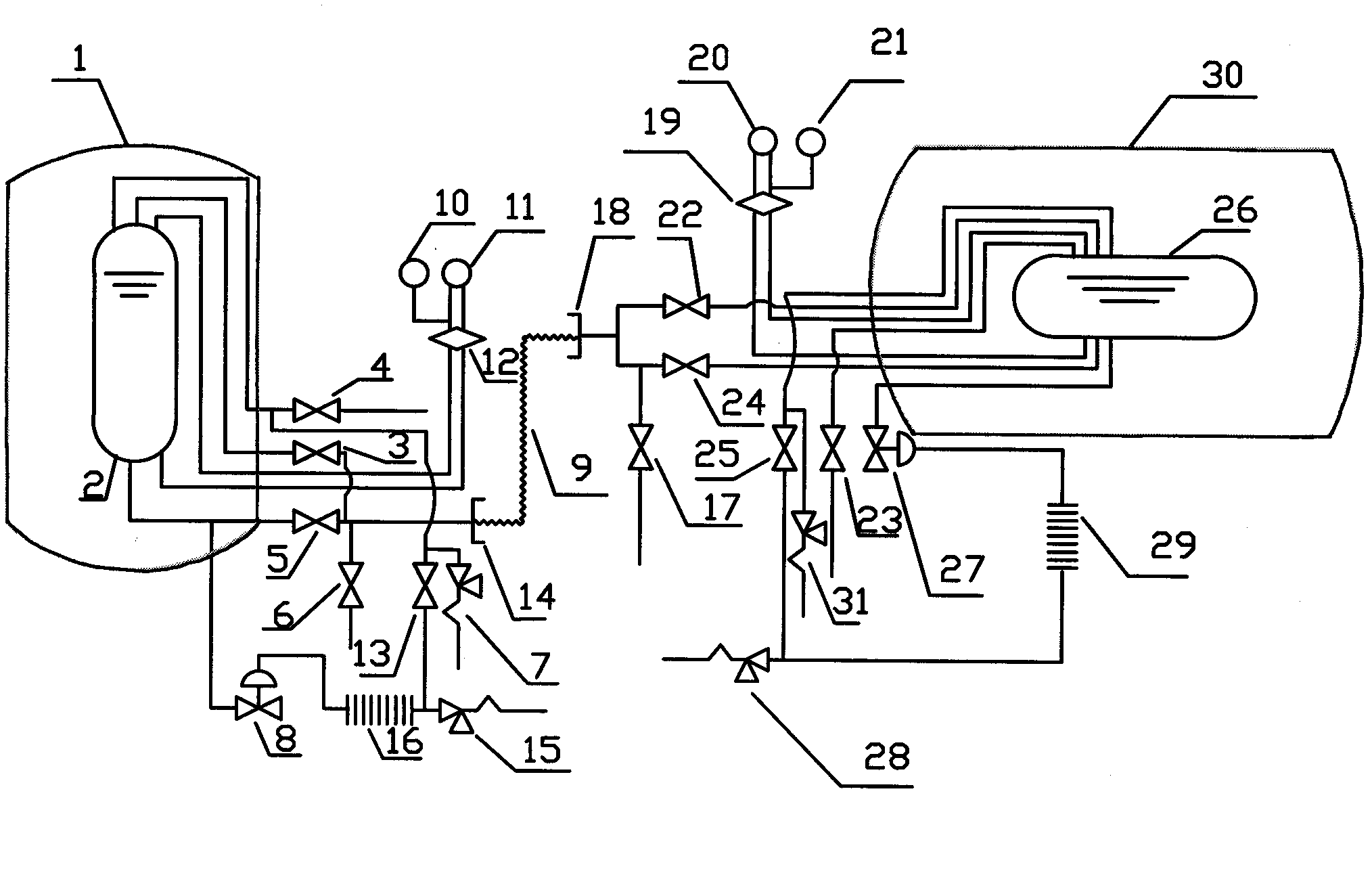
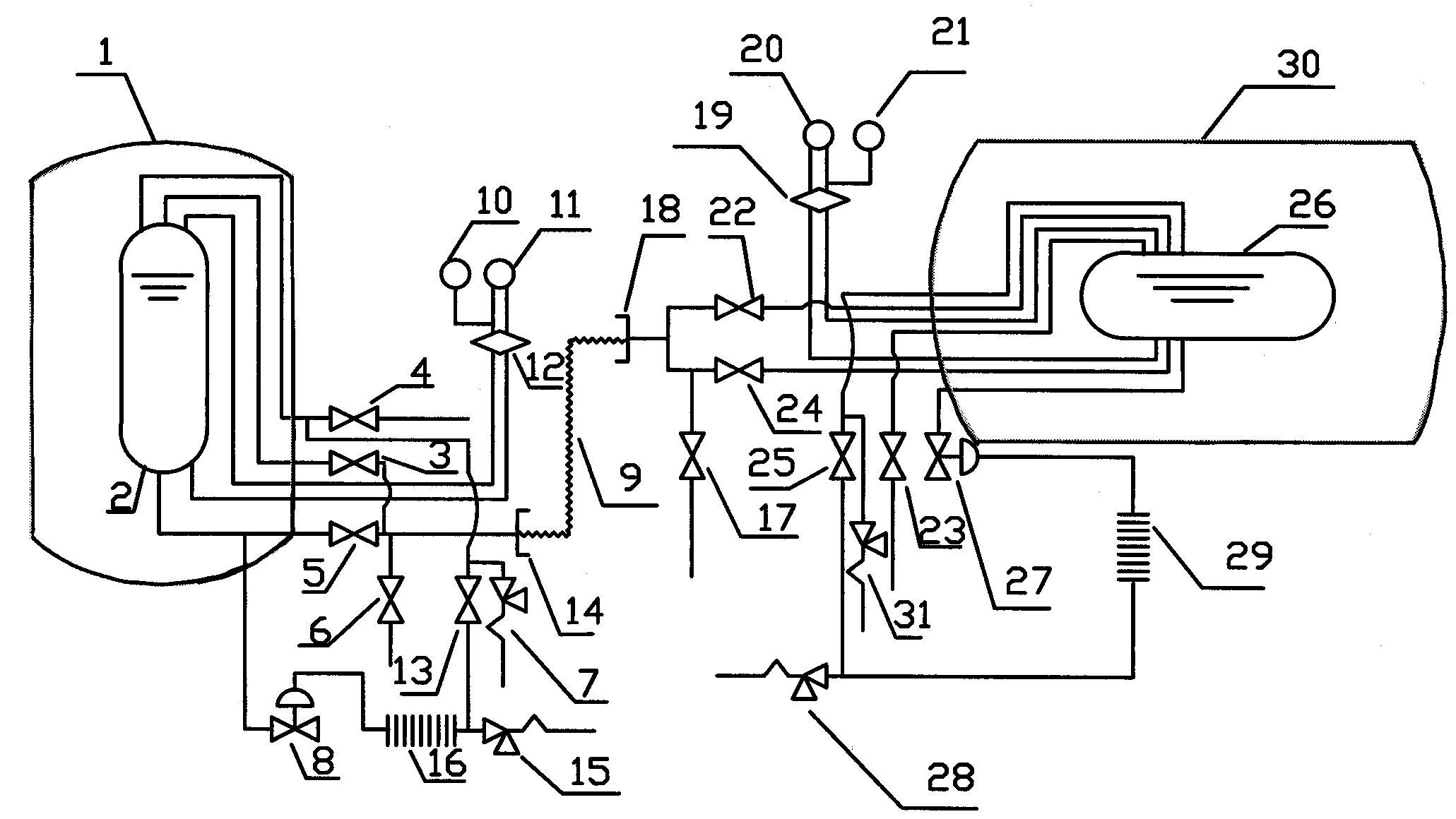
[0024] See figure 1 The filling interface 14 on the low-temperature storage tank 1 used by the customer is connected with the filling interface 18 on the tank car 30 that the manufacturer sends the low-temperature liquid through the infusion pipeline 9, in order to transport the low-temperature liquid in the tank car 30 to the customer in storage tank 1. The cryogenic liquid is only stored in the inner tank 2 of the storage tank 1 and the inner tank 26 of the tank car 30. Normally, the upper part of the inner tank 2 and the inner tank 26 is a low-temperature gas, and the lower part is a cryogenic liquid. Customers can choose according to actual needs. Choose to use liquid or gaseous gases. The storage tank 1 and the tank car 30 have the same structure, both of which are composed of an inner tank and an outer tank. There is a vacuum between the inner tank and the outer tank to achieve the effect of heat insulation, prevent heat from invading from the outside, and prevent the p...

Embodiment 2

[0034] See figure 1 The filling interface 14 on the low-temperature storage tank 1 used by the customer is connected with the filling interface 18 on the tank car 30 that the manufacturer sends the low-temperature liquid through the infusion pipeline 9, in order to transport the low-temperature liquid in the tank car 30 to the customer in storage tank 1. The cryogenic liquid is only stored in the inner tank 2 of the storage tank 1 and the inner tank 26 of the tank car 30. Normally, the upper part of the inner tank 2 and the inner tank 26 is a low-temperature gas, and the lower part is a cryogenic liquid. Customers can choose according to actual needs. Choose to use liquid or gaseous gases. The storage tank 1 and the tank car 30 have the same structure, both of which are composed of an inner tank and an outer tank. There is a vacuum between the inner tank and the outer tank to achieve the effect of heat insulation, prevent heat from invading from the outside, and prevent the p...


PUM


Abstract

The invention relates to an environment-friendly method for filling liquid nitrogen and liquid argon, belonging to the field of filling of low-temperature liquid. The pressure of a storage tank is transferred to a tank car since the pressure is released in a pressure returning way, so that the waste of nitrogen is avoided; the gas in the storage tank is converted into liquid by changing a plurality of different control valves when being filled, so that the noise pollution and the waste caused by releasing and discharging the pressure of nitrogen can be solved; and the difficulty that a large number of liquid nitrogen and liquid argon remained in a transfusion connecting pipe are wholly poured out is solved by adopting a gas extrusion method, so that the effects of energy saving and environment friendliness can be achieved, 12.5% of liquid nitrogen or liquid argon can be saved through the comparison of an actual test, and the environment-friendly method is simple and easy to operate.

Description

technical field [0001] The invention relates to an environment-friendly method for filling liquid nitrogen and liquid argon, which belongs to the field of low-temperature liquid filling. Background technique [0002] At present, the low-temperature liquid filling equipment is divided into two parts: one part is the low-temperature storage tank used by the customer, and the other is the tank truck for the manufacturer to deliver the low-temperature liquid; the filling interface on the low-temperature storage tank used by the customer and the tank for the low-temperature liquid delivered by the manufacturer The filling ports on the truck are connected together through the infusion pipeline, in order to transport the cryogenic liquid in the tank truck to the customer's storage tank. The cryogenic liquid is only stored in the inner tank of the storage tank and the inner tank of the tanker. Usually, the upper part of the inner tank is cryogenic gas, and the lower part is cryogeni...

Claims


Application Information

Patent Timeline
Patent Type & Authority Applications(China)
IPC IPC(8): F17C5/02
Inventor 苏庆魁
Owner 苏庆魁
Why Eureka
Try Eureka