Automated testing system and method for index parameters of fiber optic gyro

An automated testing and fiber optic gyro technology, applied in measurement devices, instruments, etc., can solve the problems of unintuitive test results, low degree of automation, and low test data accuracy, and achieve simple and easy test operation, improve the degree of automation, and shorten the test. effect of time

Inactive Publication Date: 2012-02-15
XIDIAN UNIV
View PDF3 Cites 18 Cited by
  • Summary
  • Abstract
  • Description
  • Claims
  • Application Information

AI Technical Summary

Problems solved by technology

[0003] At present, there are some fiber optic gyroscope parameter acquisition and testing systems, such as USB-based fiber optic gyroscope test system, RS-232-based fiber optic gyroscope test system, etc. Although these test systems can complete the basic parameter testing of fiber optic gyroscope, there are some Inadequacies, such as the RS-232-based fiber optic gyroscope test system, although the connection is simple, but the data transmission rate is slow, making it a bottleneck for high-speed data transmission; although the USB-based fiber optic gyroscope test system can simultaneously solve the problem of transmission rate, unit time, etc. The problem of data throughput, but its hardware circuit is relatively complex, and the accuracy of test data is low
In addition, there is another shortcoming in these two test systems: the degree of automation is low, the temperature box and the turntable must be controlled manually, and the recording, processing and analysis of test data are also done manually, which takes a lot of time to make data The analysis makes the operation steps more complicated during the test, prolongs the test time, and the test results are not intuitive

Method used


Image

  • Automated testing system and method for index parameters of fiber optic gyro
  • Automated testing system and method for index parameters of fiber optic gyro
  • Automated testing system and method for index parameters of fiber optic gyro

Examples


Embodiment Construction

[0030] The present invention is described in detail below in conjunction with accompanying drawing:

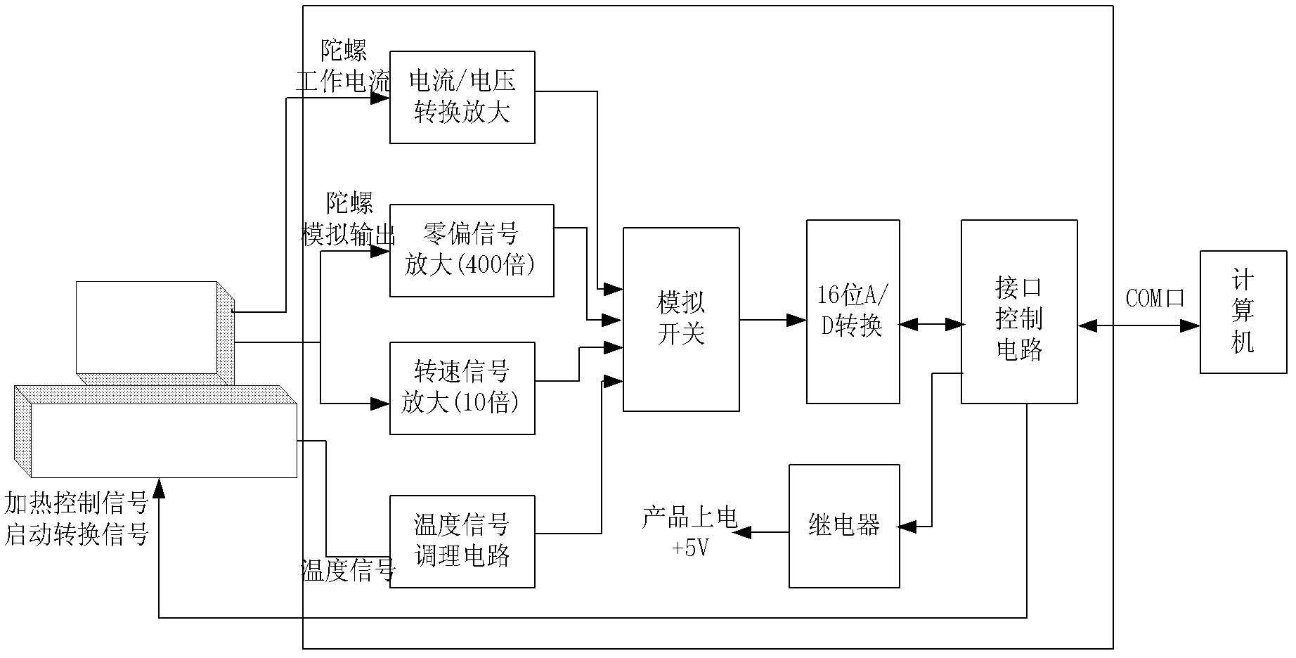
[0031] refer to figure 1 , The test system of the present invention includes three parts: an incubator turntable, a signal processing unit and a computer. The thermostat turntable is composed of a temperature controller and a turntable. The turntable is fixed on the temperature controller to provide a certain angle of rotation for the fiber optic gyroscope. The output voltage of the fiber optic gyroscope is proportional to the rotation speed of the turntable. Therefore, the collected The voltage of the fiber optic gyro corresponds to the speed of the speed. When the speed changes sinusoidally, the voltage obtained also changes sinusoidally. When the turntable is triggered and rotated each time, the area of ​​the sinusoidal curve is calculated to obtain the scale of the fiber optic gyro. Coefficient, because the heat from the heating motor is transmitted to the fiber optic gyr...


PUM


Abstract

The invention discloses an automated testing system and method for index parameters of a fiber optic gyro, mainly solving the problems of low testing precision, operation complexity, non-visual testing results and low automation degree of the prior art. The method comprises the following implementation processes of: (1) setting parameters of a turntable and a temperature controller; (2) favorablyplacing liquid nitrogen and respectively acquiring static data and dynamic data of the fiber optic gyro by taking 20 seconds as a cycle; (3) cooling to -30 DEG C and interrupting a power supply for 5min fro the fiber optic gyro; (3) restarting a test, processing data acquired in a whole testing process, and displaying and saving the processed data in the form of images; and (4) fitting the data of the fiber optic gyro and displaying a fitting result. According to the invention, precise testing data of the fiber optic gyro can be obtained, equipment is simple to operate and is feasible, the complexity in manual operation is reduced, the testing time is shortened, the high-automation testing system is realized, and the system and the method disclosed by the invention can be applied to the aerospace field and aircraft control systems.

Description

technical field [0001] The invention belongs to the technical field of data collection and testing, in particular to an automatic testing system and method for fiber optic gyroscope index parameters, which can be used in the aerospace field and aircraft control systems. Background technique [0002] Fiber optic gyro has a series of advantages such as high precision, strong anti-interference ability, and short warm-up time. It has been widely used in aerospace and other fields. It determines the accuracy of aircraft navigation and attitude control, and its quality directly affects Reliability of aircraft control systems. Therefore, the performance parameter test of fiber optic gyroscope occupies a pivotal position for fiber optic gyroscope and becomes one of the most basic technologies in this field. Therefore, a set of high-precision test system becomes an indispensable equipment for fiber optic gyroscope parameter testing. [0003] At present, there are some fiber optic gy...

Claims


Application Information

Patent Timeline
Patent Type & Authority Applications(China)
IPC IPC(8): G01C25/00
Inventor 初秀琴曹阳孔聪王飞范振军
Owner XIDIAN UNIV
Why Eureka
Try Eureka