Movable connector with self-locking device

A technology of self-locking device and connector, which is applied to the parts, connections, coupling devices, etc. of the connection device, which can solve the problems of poor connection reliability and inconvenient use, and achieve the effect of stable connection, good reliability and convenient use

Active Publication Date: 2012-02-15
杭州泰宏新能源技术有限公司
View PDF6 Cites 29 Cited by
  • Summary
  • Abstract
  • Description
  • Claims
  • Application Information

AI Technical Summary

Problems solved by technology

[0003] The purpose of the present invention is to solve the problem of poor connection reliability of the prior art movable connector and provide a movable connector with a stable connection and good reliability with a self-locking device
[0004] Another object of the present invention is to solve the problem that the connectors in the prior art need to be locked or unlocked by tools, and it is inconvenient to use, and provide a self-locking device that can be automatically locked and unlocked without tools. Connector

Method used


Image

  • Movable connector with self-locking device
  • Movable connector with self-locking device
  • Movable connector with self-locking device

Examples


Embodiment 1

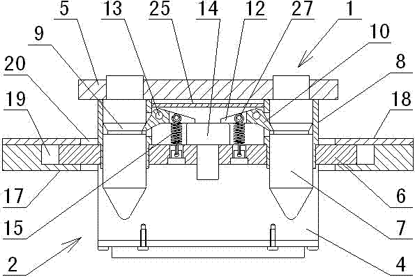
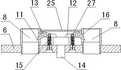
[0029] in such as figure 1 In the shown embodiment, a floating connector with a self-locking device includes a plug device 1 and a socket device 2, the plug device includes a plug 3 and a plug mounting plate 5, the plug is rectangular, and the plug is There are two 300-ampere high-current plug-ins 30 and 30 30-ampere small-current plug-ins 31, of which 8 small-current plug-ins are located in the center of the plug and are provided with a shielding device 32 on the periphery. The plug-ins here are pins. Correspondingly, The socket is also rectangular and has a socket structure corresponding to the pins. One side of the plug on the plug mounting plate is provided with a guide column pair including two guide columns 7, and a locking groove 9 of an annular structure is provided on the guide column. The cross section of the locking groove is a right-angled trapezoidal structure, and the locking groove The upper side wall forms a conical surface, and the lower side wall forms a tor...

Embodiment 2

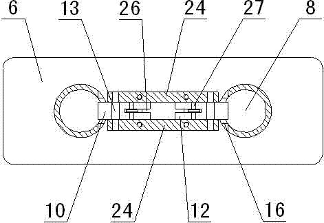
[0034] Embodiment 2 adopts two guide column pairs, and the guide columns are symmetrically arranged on both sides of the plug, and correspondingly, two guide cylinder pairs are symmetrically arranged on both sides of the plug (see Figure 9 ), and the rest are the same as in Example 1.

[0035] The socket mounting plate in the present invention is fixed on the floating seat through the floating tension spring, so that the socket mounting plate can move relatively on the floating seat, so that the guide cylinder and the corresponding socket fixed on the socket mounting plate can also be installed with the socket The plate moves relative to the floating seat. When the plug device and the socket device on the floating connector are plugged in, if there is no alignment between the plug and the socket, that is, when the guide post and the guide cylinder are not aligned accurately, since the guide post first contacts the guide cylinder, as long as the guide The position of the c...


PUM


Abstract

The invention discloses a movable connector with a self-locking device. The movable connector is characterized in that a plug mounting board is provided with a guide post pair; locking grooves with annular structures are arranged on the guide posts; a socket mounting board arranged on a movable seat is provided with a guide cylinder pair and a locking mechanism; the locking mechanism comprises a pair of symmetrically arranged locking claw; one end of the locking claw is a lock hook; the side wall of the locking mechanism close to the guide cylinder is provided with a window adaptive with the lock hook; when the movable connector is connected and locked, the lock hook passes through the window, and the end part of the lock hook is located in the locking grooves on the guide posts. By usingthe movable connector, the problems that the movable connector is lack of a locking device and the connection reliability is weak, and the connector is not convenient to use because that the connector is locked or unlocked with the aid of tools in the prior art, can be effectively solved. The movable connector provided by the invention is stable in connection and good in reliability, can be self-locked after the connector is plugged, and can be unlocked without any tools, thus, the use is very convenient.

Description

technical field [0001] The invention relates to a connector, in particular to a movable connector with a self-locking device. Background technique [0002] The plugs and sockets in the connectors of the prior art need to be aligned accurately before they can be effectively mated. If the direction deviation is too large, it will be difficult for the plug to be inserted into the socket, and sometimes the plug or socket may even be damaged during the mating process. In addition, commonly used electrical connectors are mostly used in electrical equipment with a fixed relative position between the plug and the socket, but in some electrical equipment, small-scale vibrations or relative offsets often occur between the plug and the socket, while ordinary The connector is prone to connection failure under such working conditions, so that the plug and socket in the connector cannot be reliably connected, thereby affecting the normal operation of the device. In this case, a floating...

Claims


Application Information

Patent Timeline
Patent Type & Authority Applications(China)
IPC IPC(8): H01R13/629H01R13/639
Inventor 王吉国
Owner 杭州泰宏新能源技术有限公司
Why Eureka
Try Eureka