
Device and method for utilizing recovered pressure energy and inertia energy of pneumatic tire and application

A technology of pneumatic tires and energy recovery devices, applied in tire measurement, control devices, tire parts, etc., can solve problems such as hidden safety hazards and not being well recycled.

Inactive Publication Date: 2012-02-22
郑乃时 +3
View PDF10 Cites 9 Cited by
  • Summary
  • Abstract
  • Description
  • Claims
  • Application Information

AI Technical Summary

Problems solved by technology

[0002] Nowadays, in addition to rail cars and tracked cars, most wheels have tires, which are composed of hubs and carcass. Due to the gravity of the car, when the inflatable elastic wheel assembly is rolling under load, the tires contact the road surface. Extrusion, centripetal shrinkage and deformation, leaving the road and returning to its original shape, this kind of deformation is elastic deformation, the deformation of the tire plays a role in cushioning and smooth driving, this kind of deformation is necessary, but there is a "deformation zone" where it touches the ground The available ground reaction force against the tire and the energy released when the tire returns to its original shape have not been well recycled
[0003] The domestic patent CN101850698A discloses a power generation tire. By setting a permanent magnetic ring, an electromagnetic ring and a coil on the wheel hub, the patent can generate electricity by itself when the tire rotates and prevent the flat tire through magnetic repulsion. The deflated design makes it need to be used in the case of remodeling the car body and brings safety hazards to users, and its magnetic repulsion anti-flat tire can only be a slight recovery when it is normally deformed

Method used


Image

  • Device and method for utilizing recovered pressure energy and inertia energy of pneumatic tire and application
  • Device and method for utilizing recovered pressure energy and inertia energy of pneumatic tire and application
  • Device and method for utilizing recovered pressure energy and inertia energy of pneumatic tire and application

Examples


Embodiment Construction

[0101] The present invention will be further described with reference to the accompanying drawings, and the manufacturing technology of such a device will be very clear to those skilled in the art.

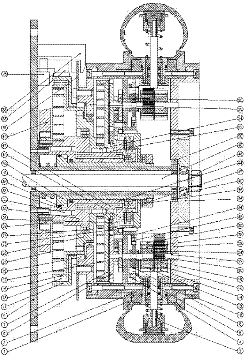
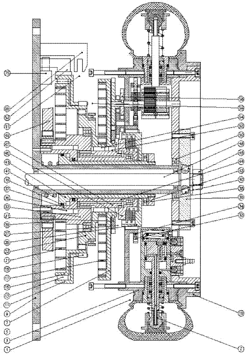
[0102] Now take the single-end support pneumatic tire as an example:

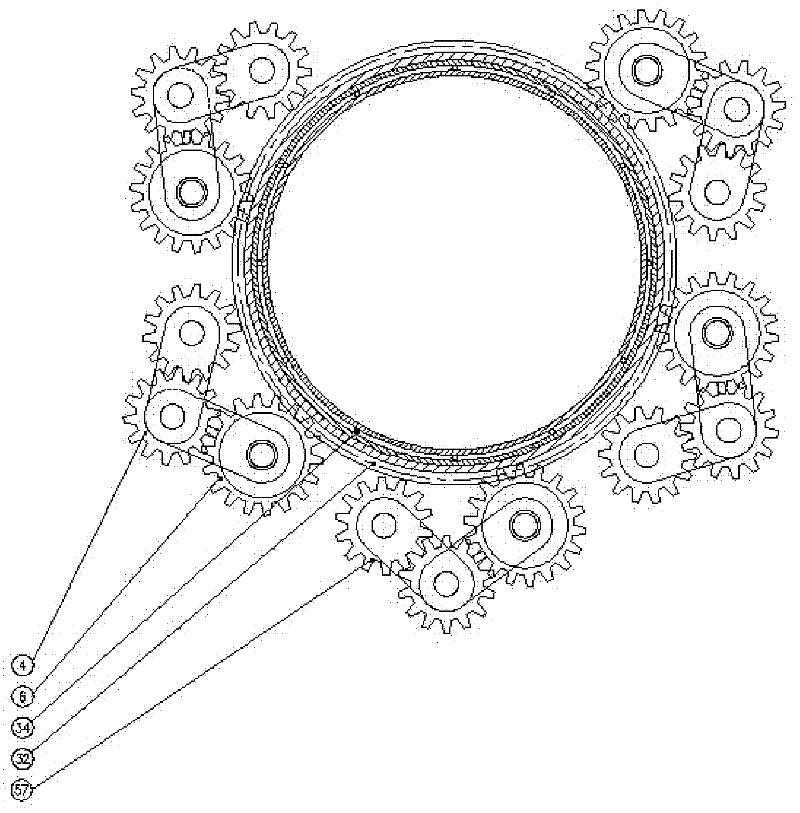
[0103] like figure 1 , figure 2 As shown in the figure, the present invention includes a combined wheel body, a wheel spindle, and a pneumatic tire pressure energy recovery device. The pneumatic tire pressure energy recovery device is composed of a number of energy harvesting devices arranged in a vacuum tire. The pressure energy utilization device also includes a recovery pressure transmission integration device, including a recovery pressure transmission direction integration device, a recovery pressure balance integration device, a recovery pressure transmission linear speed integration device, an inertial energy recovery device, a working condition control device, and a tire condition monitoring device. ...


PUM


Abstract

The invention relates to the technical field of recovery and utilization of pressure energy and inertia energy of a pneumatic tire, in particular to a device and a method for utilizing recovered pressure energy and inertia energy of a pneumatic tire. The device comprises a combined type wheel body, a wheel spindle and a pneumatic tire pressure energy recovery device, wherein the pneumatic tire pressure energy recovery device is arranged on an inner ring of the combined type wheel body and is formed by a plurality of energy capturing devices arranged in a vacuum tire, and each energy capturing device is internally provided with an energy capturing rod. The device for utilizing the recovered pressure energy and the recovered inertia energy is characterized by also comprising a recovered pressure transmission and integration device, an inertia energy recovery and utilization device, a working condition operating control device, and a tire working condition monitoring device. The device provided by the invention has a novel structure, the pressure energy and the inertia energy of the tire can be effectively utilized through interaction of the energy capturing devices, and the device can well adapt to various conditions such as acceleration, braking, deceleration and the like.

Description

[Technical field] [0001] The patent of the present invention relates to the technical field of recovering and utilizing pressure and inertial energy of pneumatic tires, in particular to a utilization device, method and application for recovering pressure energy and inertial energy of pneumatic tires. [Background technique] [0002] Nowadays, except for rail cars and crawler cars, most of the wheels have tires. This kind of tire is composed of a wheel hub and a carcass. Due to the gravity of the vehicle, when the pneumatic elastic wheel assembly is rolling under load, the tire contacts the road surface. Squeeze, shrink and deform centripetally, and return to its original shape when it leaves the road. This deformation is elastic deformation. The deformation of the tire plays a role in buffering and smooth driving. This deformation is necessary, but it exists in the "deformation zone" of its landing. With the reaction force of the available ground against the tire and the ener...

Claims


Application Information

Patent Timeline
IPC IPC(8): B60K25/08B60C23/04B60C19/00
Inventor 郑乃时郑雯倩郑朝晖蔡体刚
Owner 郑乃时
Learn More