
Power supply system for electric locomotive

A technology of power supply system and electric locomotive, which is applied to electric locomotives, locomotives, motor vehicles, etc., and can solve problems such as railway line congestion and electric locomotives being unable to operate

Active Publication Date: 2012-02-22
SHENZHEN INVT TRANSPORTATION TECH CO LTD
View PDF5 Cites 39 Cited by
  • Summary
  • Abstract
  • Description
  • Claims
  • Application Information

AI Technical Summary

Problems solved by technology

In this way, when the electric locomotive cannot obtain power from the catenary, the storage battery 27 can supply power to emergency systems such as emergency lighting and ventilation equipment to maintain emergency power consumption. You can only stop the operation and wait for the trailer to be towed away. During the peak operation period, it may even lead to the blockage of the railway line, resulting in more serious consequences

Method used


Image

  • Power supply system for electric locomotive
  • Power supply system for electric locomotive
  • Power supply system for electric locomotive

Examples


Embodiment Construction

[0022] In order to enable those of ordinary skill in the art to more clearly understand the purpose, technical solutions, and advantages of the present invention, the present invention will be further described below with reference to the accompanying drawings and embodiments.

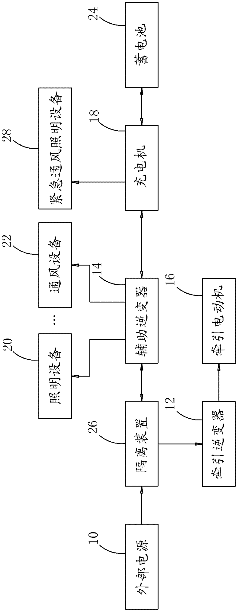
[0023] The present invention is based on the existing electric locomotive power supply system and mainly changes the structure of the charger, so that the battery can be used to supply power to the traction motor when necessary (for example, when the contact network fails to obtain electricity). Slow exercise of electric locomotive. See image 3 As shown, the electric locomotive power supply system disclosed in the present invention includes an external power supply 10, which is used to step-down and rectify the high-voltage alternating current of the catenary into direct current with a predetermined voltage value (for example, 1500v), and preferably through an isolation device 26 The load is applied to t...


PUM


Abstract

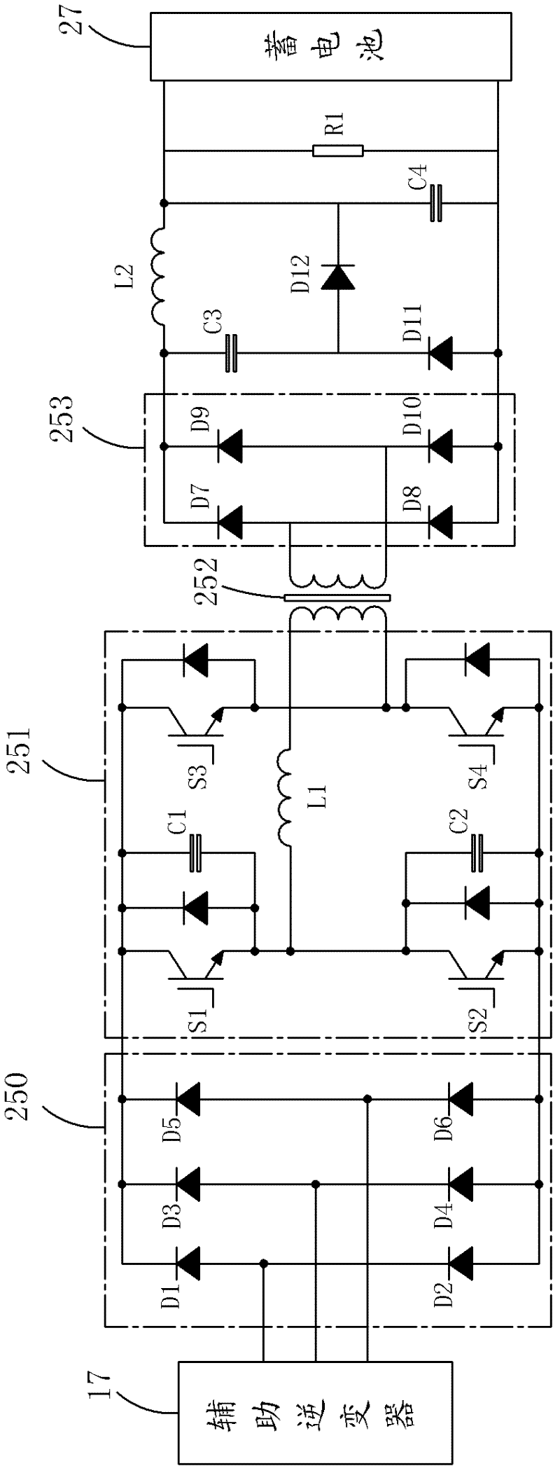
The invention discloses a power supply system for an electric locomotive. The power supply system comprises an external power supply, a traction invertor, an auxiliary invertor and a charger, wherein the charger comprises a first three-phase bridge-type inversion circuit; the alternating current side of the first three-phase bridge-type inversion circuit is connected with the low voltage side of a first three-phase transformer and the direct current side of the first three-phase bridge-type inversion circuit is connected with a storage battery; and the high voltage side of the first three-phase transformer is coupled to the output end of the auxiliary invertor. The power supply system for the electric locomotive can supply power to a traction motor by using the storage battery when a contact network fails; and low speed running of the electric locomotive can be retained.

Description

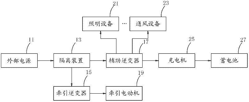
Technical field [0001] The invention belongs to a power supply system, in particular to a power supply system for electric locomotives. Background technique [0002] Common electric locomotive power supply systems such as figure 1 As shown, the external power supply 11 steps down and rectifies the high-voltage alternating current from the catenary into direct current with a predetermined voltage value (for example, 1500v), and loads it to the traction inverter 15 and the auxiliary inverter 17 through the isolation device 13. The traction inverter 15 converts the input direct current of 1500v into three-phase alternating current and then drives the traction motor 19 to drive the electric locomotive. The auxiliary inverter 17 inverts, step-downs and converts the 1500v input DC power into three-phase AC power and supplies it to the load equipment of the auxiliary power supply system, such as lighting equipment 21, ventilation equipment 23, etc., of which one is the input of the char...

Claims


Application Information

Patent Timeline
IPC IPC(8): B60L9/00B60L11/18B60L1/00B61C3/00
CPCY02T10/70Y02T10/72
Inventor 唐传明杨北辉沈建华
Owner SHENZHEN INVT TRANSPORTATION TECH CO LTD
Learn More