Flying saucer aircraft

A technology for an aircraft and a flying saucer, applied in the field of aircraft, can solve the problems of not running smoothly, comfortably, discharging harmful waste gas, and being unfavorable to environmental protection, and achieve the effects of being beneficial to environmental protection, low maintenance and energy consumption costs, and saving construction costs.

Inactive Publication Date: 2012-02-22
梁锡球
View PDF9 Cites 4 Cited by
  • Summary
  • Abstract
  • Description
  • Claims
  • Application Information

AI Technical Summary

Problems solved by technology

[0002] Some of the existing flying saucer-shaped aircraft adopt the jet mode and some adopt the rotor mode to generate lift and propulsion, but both of them have the disadvantages of running not stable enough, comfortable, and difficult to realize automatic control; the noise is large, and harmful exhaust gas is emitted, which is not conducive to environmental protection. Waiting for deficiencies

Method used


Image

  • Flying saucer aircraft
  • Flying saucer aircraft
  • Flying saucer aircraft

Examples


Embodiment 1

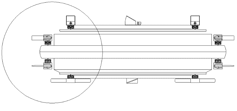
[0030] like Figure 1 to Figure 14 As shown, the first embodiment of the flying saucer aircraft of the present invention includes a disk-shaped (two interlocking dish-shaped) shell 1, and the shell 1 has a built-in power supply (not shown), and the power source is a combination of a nuclear reactor and a generator or Combustion engine combined with generator or battery.

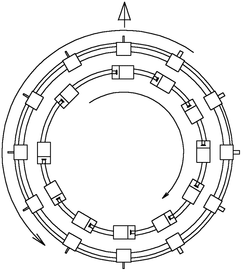
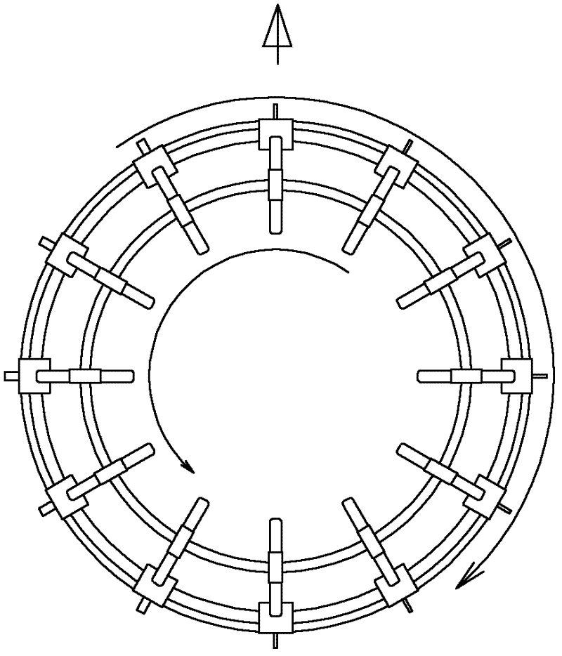
[0031] see Figure 1 to Figure 4 There are four annular ferromagnetic guide rails 2, 3, 4, and 5 on the outer surface of the housing 1: upper inner, upper outer, lower inner and lower outer.

[0032] The upper inner annular ferromagnetic guide rail 2 is provided with a plurality of lifting force generating vehicles 6, and the structure is as follows: the vehicle body is a rectangular tube with a horizontal axis and tangent to the annular ferromagnetic guide rail, and the top panel of the rectangular tube is high in front and low in the back so as to be generated in the wind. Lifting force, the bottom of the...


PUM


Abstract

The invention discloses a flying saucer aircraft. The flying saucer aircraft comprises a disc-shaped housing, wherein a power supply is arranged in the disc-shaped housing and an upper inner annular ferromagnetic guide rail, an upper outer ferromagnetic guide rail, a lower inner ferromagnetic guide rail and a lower outer ferromagnetic guide rail are arranged on an outer surface of the disc-shaped housing. The flying saucer aircraft adopts a stable driving force production way, is easy for realization of automatic control, does not produce noise, does not discharge harmful gas, is beneficial for environmental protection, saves construction funds, and reduces operation, maintenance and energy consumption costs.

Description

technical field [0001] The present invention relates to an aircraft, in particular to a flying saucer-shaped aircraft. Background technique [0002] Some of the existing flying saucer-shaped aircraft use the jet method and some use the rotor method to generate lift and propulsion, but both of them are not stable and comfortable to operate, and it is difficult to realize automatic control; the noise is large, and harmful waste gas is discharged, which is not conducive to environmental protection. Wait for the inadequacies. [0003] In addition, the synchronous linear motor and maglev technology are relatively mature technologies, such as maglev trains, with electromagnets installed on the car body and coils installed at the bottom of the guide rail. After power-on, the polarity of the magnetic field generated by the guide rail coil is always the same as the polarity of the electromagnet on the car body. There are also coils on both sides of the rail, and the alternating cu...

Claims


Application Information

Patent Timeline
Patent Type & Authority Applications(China)
IPC IPC(8): B64C39/06B64D27/02
Inventor 梁锡球
Owner 梁锡球
Why Eureka
Try Eureka