Transmission structure of PTZ (Pan/Tilt/Zoom) camera

A technology of pan-tilt camera and transmission structure, which is applied in the field of cameras, and can solve problems such as eccentricity, long force-bearing structure of the rotating shaft, displacement of the rotating shaft, etc., and achieve the effects of reducing production costs, smooth and stable rotating process, and simple matching structure

Inactive Publication Date: 2012-02-22
TIANJIN TIANDY DIGITAL TECH
View PDF5 Cites 3 Cited by
  • Summary
  • Abstract
  • Description
  • Claims
  • Application Information

AI Technical Summary

Problems solved by technology

[0007] In the structure of the prior art, the motor shaft and the rotating shaft are generally connected by a belt, and the motor directly drives the rotating shaft to rotate through the belt. The force-bearing structure of the rotating shaft is relatively long, and eccentricity easily occurs during installation and rotation. phenomenon, and the position of the rotating shaft relative to the bearing during rotation cannot be accurately defined, and it is easy to cause the rotating shaft to shift during the operation of the gimbal

Method used


Image

  • Transmission structure of PTZ (Pan/Tilt/Zoom) camera
  • Transmission structure of PTZ (Pan/Tilt/Zoom) camera
  • Transmission structure of PTZ (Pan/Tilt/Zoom) camera

Examples


Embodiment Construction

[0022] The present invention will be described in detail below with reference to the drawings and examples.

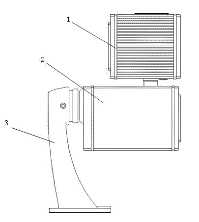
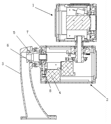
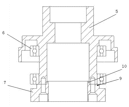
[0023] figure 1 It is a schematic diagram of the external structure of the PTZ camera; figure 2 It is the internal schematic diagram of the pan-tilt camera that has adopted the transmission structure of the pan-tilt camera of the present invention; image 3 It is a sectional view of the transmission structure of the pan-tilt camera of the present invention; Figure 4 It is a partial enlarged view of the rotating shaft and the synchronous belt pulley in the assembly position in the transmission structure of the pan-tilt camera of the present invention; Figure 5 It is a sectional view of the synchronous belt pulley in the transmission structure of the pan-tilt camera of the present invention.

[0024] Such as Figure 1 to Figure 5 Shown, the transmission structure of the pan-tilt camera of the present invention, wherein above-mentioned pan-tilt camera comprises: ca...


PUM


Abstract

The invention relates to a transmission structure of a PTZ (Pan/Tilt/Zoom) camera, wherein the PTZ camera comprises a camera, a cloud platform and a supporting base; a motor and a rotating shaft are arranged in the cloud platform; a synchronous belt pulley is fixedly arranged at one end of the rotating shaft, which is positioned inside the cloud platform; the motor is in drive connection with the synchronous belt pulley through a belt; when the motor operates, the rotating shaft is driven to rotate in a bearing by the synchronous belt pulley; the synchronous belt pulley and the rotating shaft are coaxial mutually; one side of the synchronous belt pulley, which corresponds to the rotating shaft, is provided with a boss structure; a frustum is arranged on the plane of the boss; and when the synchronous belt pulley is matched with the rotating shaft, the frustum is totally inserted into a hollow structure of the rotating shaft and the plane of the boss is tightly attached to the rotating shaft. The frustum takes an assembly positioning effect in the assembling process, so that the rotating shaft and the synchronous belt pulley can be in close fit more accurately, the problem that the rotating shaft and the synchronous belt pulley are eccentrical mutually in the operating process is avoided and the rotating process of the PTZ camera in use is more smooth and stable.

Description

technical field [0001] The present invention relates to the technical field of video cameras, specifically, a synchronous belt pulley is fixed at one end of the rotating shaft, and the motor drives the synchronous belt pulley through the belt to rotate the rotating shaft and avoid the eccentricity of the rotating shaft during rotation. The transmission structure of the camera. Background technique [0002] The PTZ is a camera installation platform composed of two AC motors, which can drive the camera to move horizontally and vertically. There are two motors inside the gimbal, which are responsible for the up and down and left and right rotations of the gimbal respectively. The difference in working voltage also determines the overall working voltage of the gimbal, generally there are AC 24V, AC 220V and DC 24V. When receiving the up and down action voltage, the vertical motor rotates and drives the vertical transmission wheel to rotate through the reduction box; when recei...

Claims


Application Information

Patent Timeline
Patent Type & Authority Applications(China)
IPC IPC(8): F16M11/18F16M11/12H04N5/225
Inventor 戴林张秋菊
Owner TIANJIN TIANDY DIGITAL TECH
Why Eureka
Try Eureka