Optical mechanical cold connector

A splicer, mechanical technology, applied in the coupling of optical waveguides, etc., can solve the problems of the quality of optical fiber butt joint, can not be reused, reduce the performance of light, achieve small thermal expansion and contraction coefficient, reduce operating errors, improve The effect of environmental performance

Inactive Publication Date: 2013-04-17
WANMA TECH CO LTD
View PDF6 Cites 0 Cited by
  • Summary
  • Abstract
  • Description
  • Claims
  • Application Information

AI Technical Summary

Problems solved by technology

[0003] The mechanical cold splicer of this structure has the following problems: the metal sheet will naturally open outward after the peripheral crimping wedges age, reducing the light transmission performance, and at the same time the deformation of the metal sheet cannot be completely recovered, so it cannot be reused
[0005] The mechanical cold splicer with this structure has the following problems: the optical fiber is in an unfixed free state inside the circular tube. Once there is a large external pulling force or the peripheral fixed structure is aged, the optical performance will be affected.
[0007] Since the hardness of the plastic part of this structure is lower than that of the optical fiber, it is very easy to scrape off the plastic debris by the sharp end face of the optical fiber, thereby blocking the V-shaped groove or polluting the high light-transmitting liquid substance, affecting the light transmission performance and causing the quality of the optical fiber docking decline
[0008] The above types of optical fiber cold splices all require special operating tools. The tools of each manufacturer are different. unnecessary trouble

Method used


Image

  • Optical mechanical cold connector
  • Optical mechanical cold connector
  • Optical mechanical cold connector

Examples


Embodiment Construction

[0043] The present invention will be further described below in conjunction with the accompanying drawings, but the present invention is not limited to the following examples.

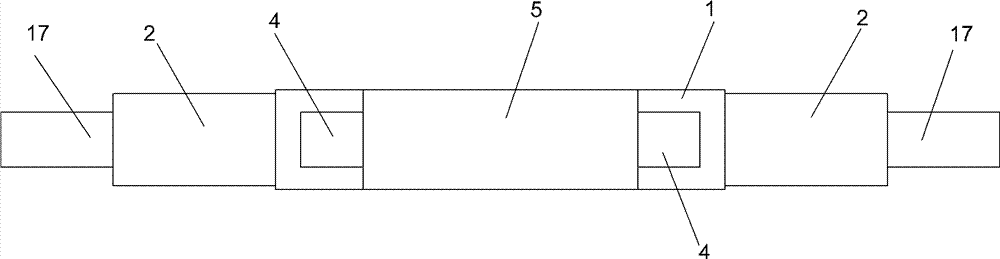
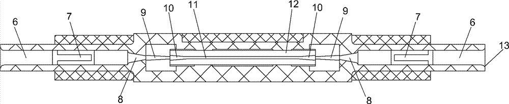
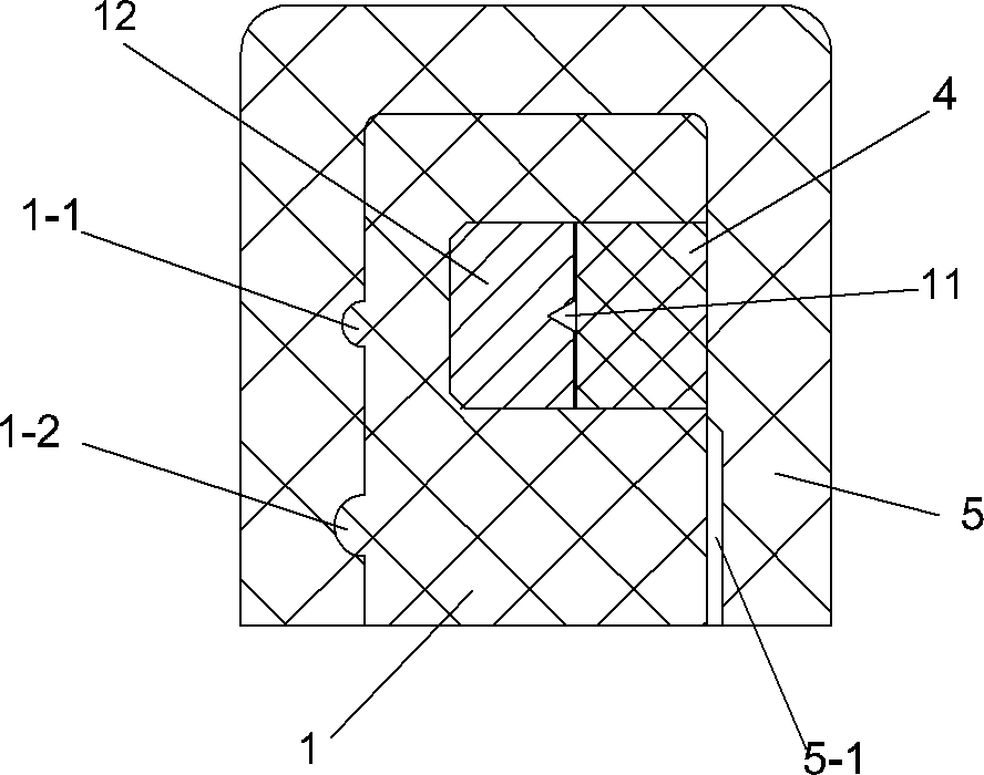
[0044] As shown in the figure, an optical fiber mechanical cold splicer according to the present invention includes a main body shell 1 (made of plastic) with a fixing groove 15 in the middle; a metal block 12 (such as Figure 6 As shown, several small bumps 16 can be made in the fixing groove, and then the metal block is pressed into the fixing groove by mechanical crimping), and the metal block is formed with a V-shaped groove 11 extending along the axis direction of the main body shell ( Conventional structure, the depth and width of the V-shaped groove are determined according to the specifications of the optical fiber), the openings of the fixing groove and the V-shaped groove are all facing the front side of the main body shell (direction reference figure 1 , outward along the paper).

[0045] S...


PUM


Abstract

The invention relates to an optical mechanical cold connector, which solves the technical problem that the provided mechanical cold connector can realize rapid and stable connection of an optical fiber without a special connection tool and has the characteristics of convenience for use and simple structure. The technical scheme is as follows: the optical mechanical cold connector is characterizedby comprising a main body housing provided with a fixed groove at the middle, wherein a metal block is embedded in the fixed groove and provided with a V-shaped groove extending along the axial line direction of the main body housing, openings of the fixed groove and the V-shaped groove face towards the front side of the main body housing, the fixed groove is internally provided with a movable pressure cover for pressing the optical fiber in the V-shaped groove, and the middle of the front side surface of the movable pressure cover is provided with a protruding pretightening block, and the left end and the right end of the movable pressure cover are embedded in movable pressure cover installation grooves at the left side and the right side of the fixed groove.

Description

technical field [0001] The invention relates to an optical fiber accessory, in particular to an optical fiber mechanical cold splice. Background technique [0002] At present, there are three kinds of mechanical cold splices used for optical fiber docking: one is to cut a fiber slot on a piece of high-precision metal sheet folded in half, and at the same time, a high-transmittance liquid substance is preset in the slot, and it passes through the peripheral pressure when docking. The splicing wedge shrinks the folded metal sheet inwards and clamps the optical fiber at the same time. Since the hardness of the metal sheet is lower than that of the optical fiber, a tight package effect will be formed at the optical fiber through the deformation of the metal sheet. [0003] The mechanical cold splicer of this structure has the following problems: the metal sheet will naturally open outward after the peripheral crimping wedges age, reducing the light transmission performance. At ...

Claims


Application Information

Patent Timeline
Patent Type & Authority Patents(China)
IPC IPC(8): G02B6/38
Inventor 徐长鑫林啸洋黄茹
Owner WANMA TECH CO LTD
Why Eureka
Try Eureka