
Distributed deployment system and method of components

A deployment system and distributed technology, applied in the field of component deployment, can solve problems such as error-prone, increased software operation and maintenance costs, waste of server resources, etc., to avoid impact and facilitate deployment.

Active Publication Date: 2012-02-22
YONYOU NETWORK TECH
View PDF5 Cites 43 Cited by
  • Summary
  • Abstract
  • Description
  • Claims
  • Application Information

AI Technical Summary

Problems solved by technology

During specific configuration, the physical deployment package (contribution), component assembly configuration file (composite), running node (Node), component assembly configuration file deployment configuration (Cloud), etc. must be manually registered, which not only increases the operation and maintenance cost of the software , it is also prone to errors, that is, the actual running state and configuration of the server are prone to inconsistencies
In addition, in terms of component instance management, there is a problem in the existing technology, that is, once the component assembly configuration file is registered to a specific running node through the domain manager, when the node starts, the corresponding component instance will be created instead of based on the inter-component Dependencies to dynamically create and start corresponding component instances, which will cause some components that are not referenced at all to be created and start services, resulting in a waste of valuable server resources
Similarly, when a component stops running, its single-line dependent component instance cannot automatically stop the service and destroy the instance, and those components that rely on this component in reverse cannot handle it accordingly (such as adopting a service stop strategy)
In addition, in a distributed environment, the configuration of server nodes is sometimes modified according to security and management needs. When dealing with such problems, the current technical framework not only requires manual restart of all components deployed on the server nodes with modified configurations, but also All other components that reference these components must be manually restarted. These components may be distributed on different server nodes. When there are complex dependencies between components, this is a very difficult task, and the management cost is high, causing administrators to Tends to reboot all servers, disrupting other otherwise functioning services

Method used

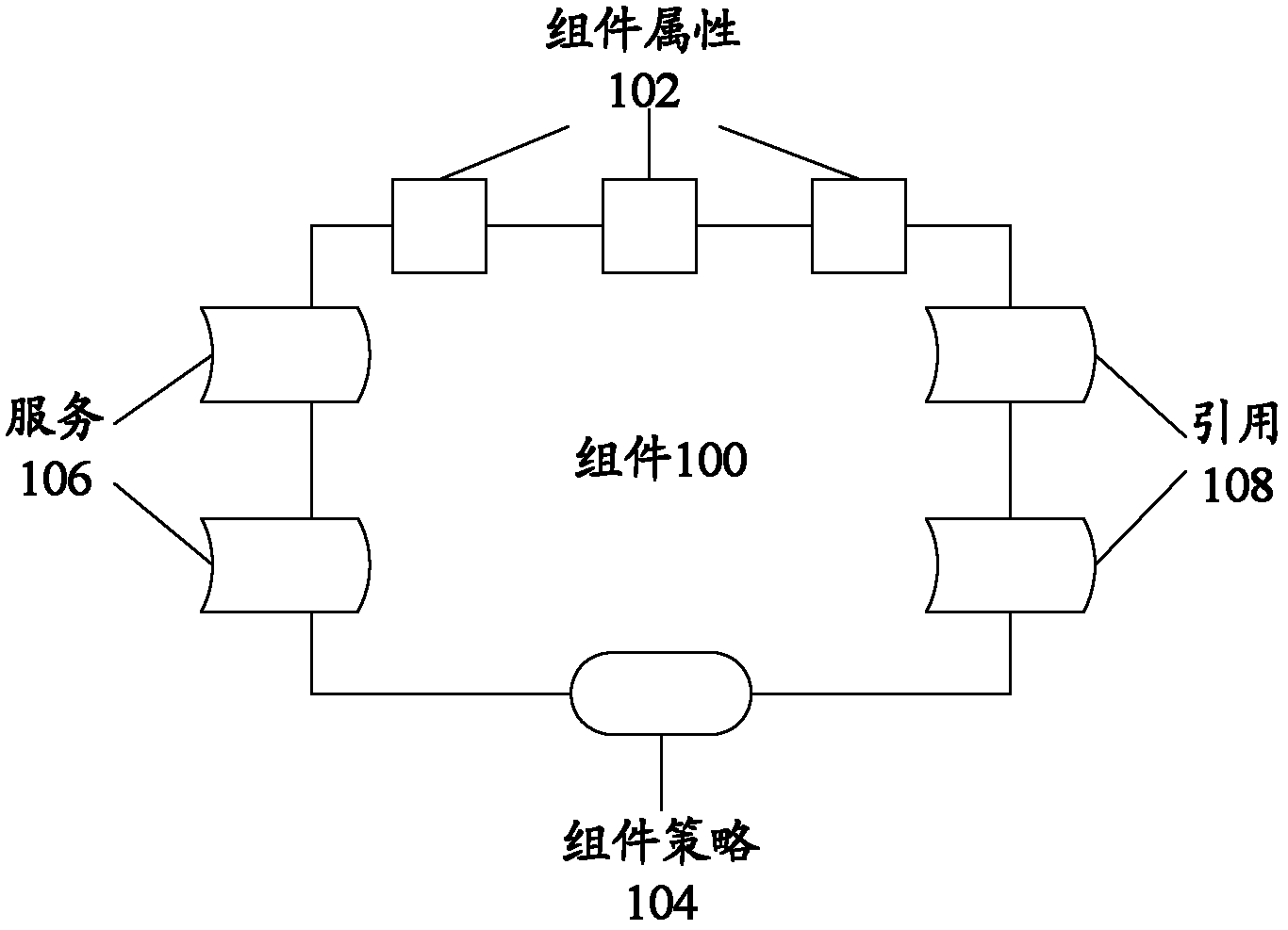

Image

  • Distributed deployment system and method of components
  • Distributed deployment system and method of components
  • Distributed deployment system and method of components

Examples


Embodiment Construction

[0031] In order to understand the above-mentioned purpose, features and advantages of the present invention more clearly, the present invention will be further described in detail below in conjunction with the accompanying drawings and specific embodiments.

[0032] In the following description, many specific details are set forth in order to fully understand the present invention, but the present invention can also be implemented in other ways different from those described here, therefore, the present invention is not limited to the specific embodiments disclosed below limit.

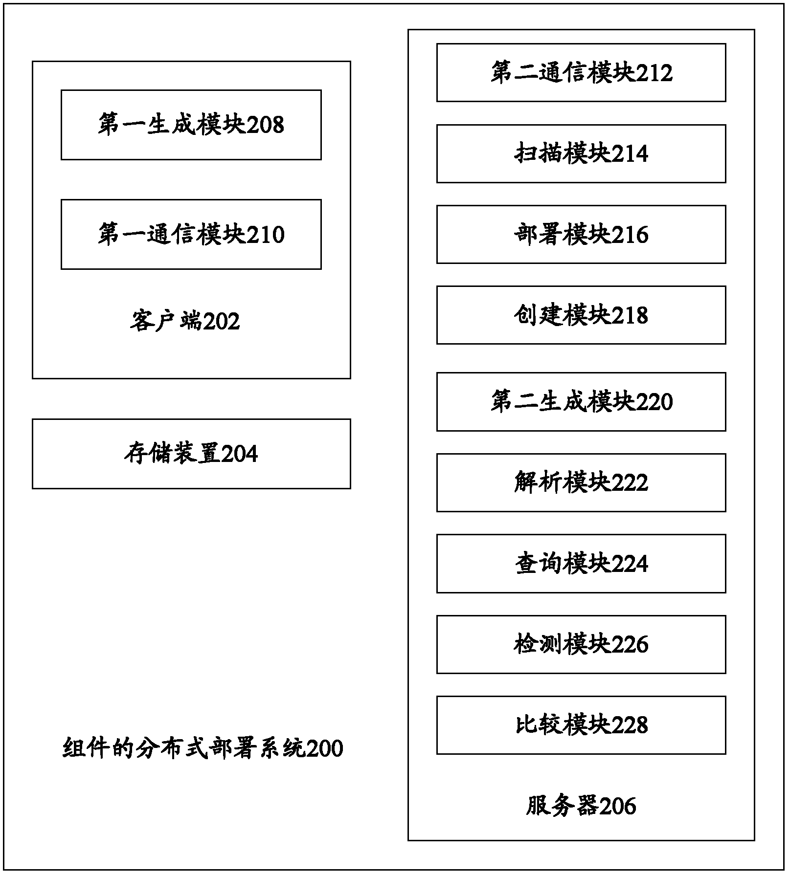
[0033] figure 2 A block diagram showing a distributed deployment system of components according to an embodiment of the invention.

[0034] Such as figure 2 As shown, the distributed deployment system 200 of components according to the embodiment of the present invention includes: a client 202, a storage device 204, and a server 206, wherein the client includes: a first generation module 208, usin...


PUM


Abstract

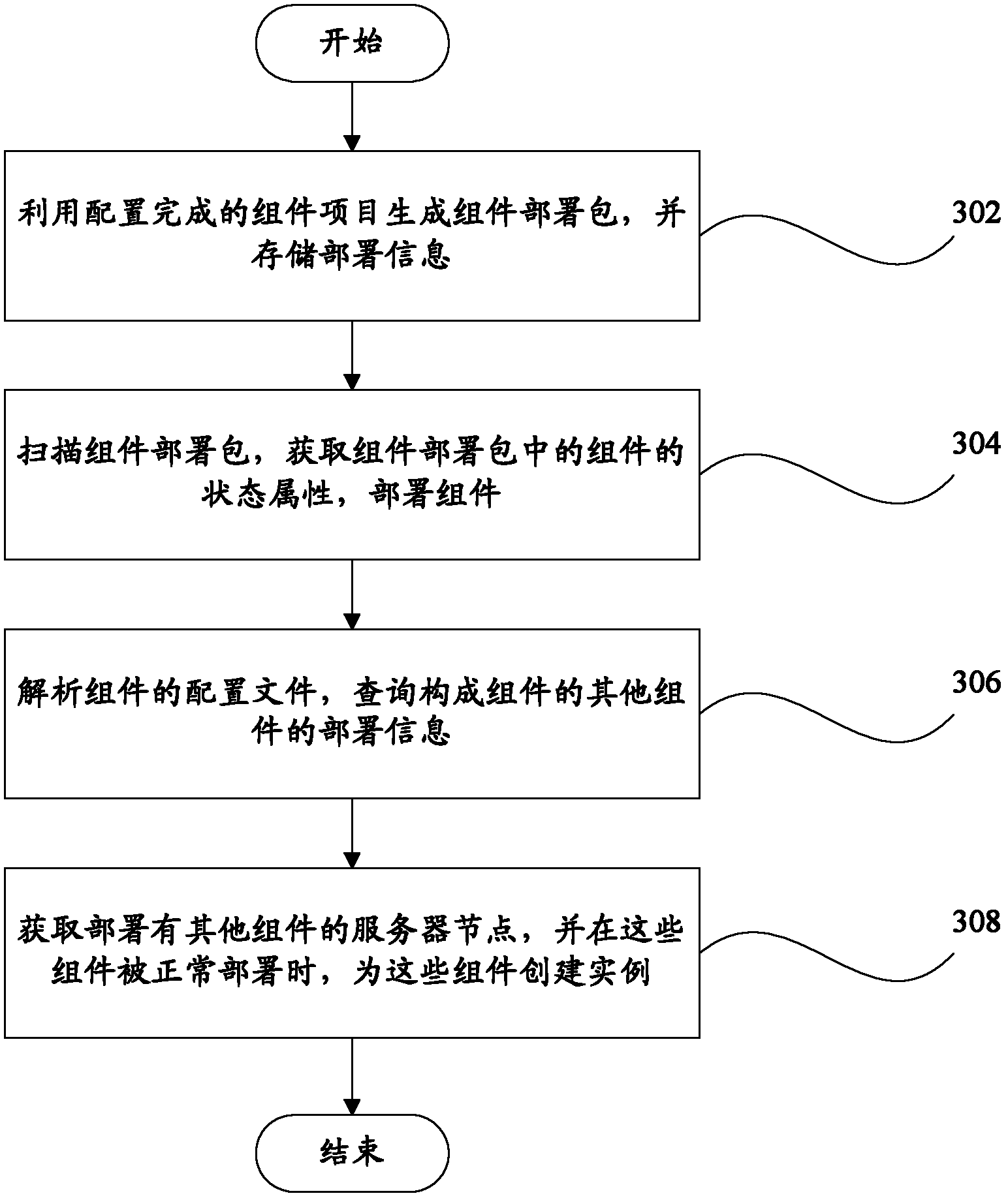
The invention discloses a distributed deployment system and method of components. The method comprises the following steps of: step 202, generating a component deployment package by a configured component project, and storing deployment information, wherein the deployment information comprises the information of the component project, the information of at least one component in the component project, the association information of a plurality of components and the information of the component deployment package; and step 204, scanning the component deployment package and obtaining state attribute of the component in the component deployment package, if the state attribute is static, deploying the static component at a corresponding server node, and if the state attribute is dynamic, deploying the dynamic component at the corresponding server node, and storing the corresponding relation between the component and the server node. With the technical scheme of the invention, the components with complex dependence relation can be conveniently deployed and instances can be managed finely in a distributed environment, simultaneously, needs-based creation and startup can be realized, andinfluences on the entire system can be avoided.

Description

technical field [0001] The present invention relates to component deployment technology, in particular, to a distributed deployment system and method of components. Background technique [0002] Component-based programming has always been an important method to enhance software reusability, scalability, and improve software development efficiency and quality. However, different languages ​​and platforms often require different component models, and components of different implementation models cannot interact directly. The purpose of SCA is to enable users to build enterprise applications without directly facing the level of specific technical details, but to build applications through service components. This method also makes the customer's enterprise application have a good layered architecture, which can well separate the business logic and IT logic of the application, which is not only easy to build the application, but also easy to change and deploy the application. T...

Claims


Application Information

Patent Timeline
IPC IPC(8): G06F9/46H04L29/08
Inventor 程操红
Owner YONYOU NETWORK TECH
Learn More