
Transformer

A transformer and metal plate technology, applied in the field of transformers, can solve the problems of complex manufacturing process of high-power transformers, rising copper wire prices, etc., and achieve the effects of convenient external lead wire connection, increased surface area, and reduced transformer thickness

Inactive Publication Date: 2012-02-22
中山普润斯电源设备技术有限公司
View PDF6 Cites 0 Cited by
  • Summary
  • Abstract
  • Description
  • Claims
  • Application Information

AI Technical Summary

Problems solved by technology

[0007] Fourth, the winding manufacturing process of high-power transformers is very complicated, and traditional manufacturing methods have great pressure on manufacturing costs
[0008] Fifth, the price of copper wires in the market continues to rise, which brings greater pressure to transformer manufacturing

Method used


Image

  • Transformer
  • Transformer
  • Transformer

Examples


Embodiment Construction

[0031] The present invention is described in detail below in conjunction with the accompanying drawings:

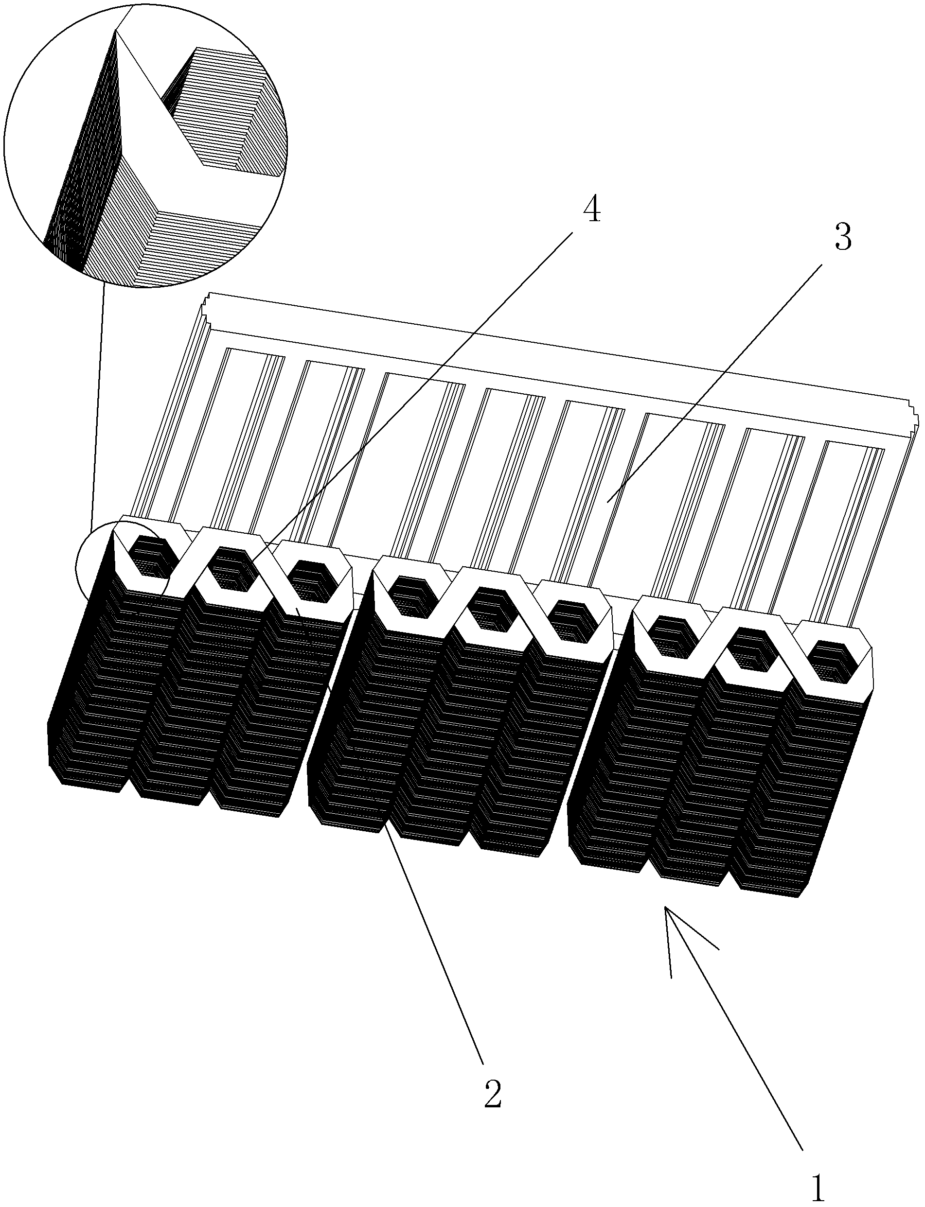
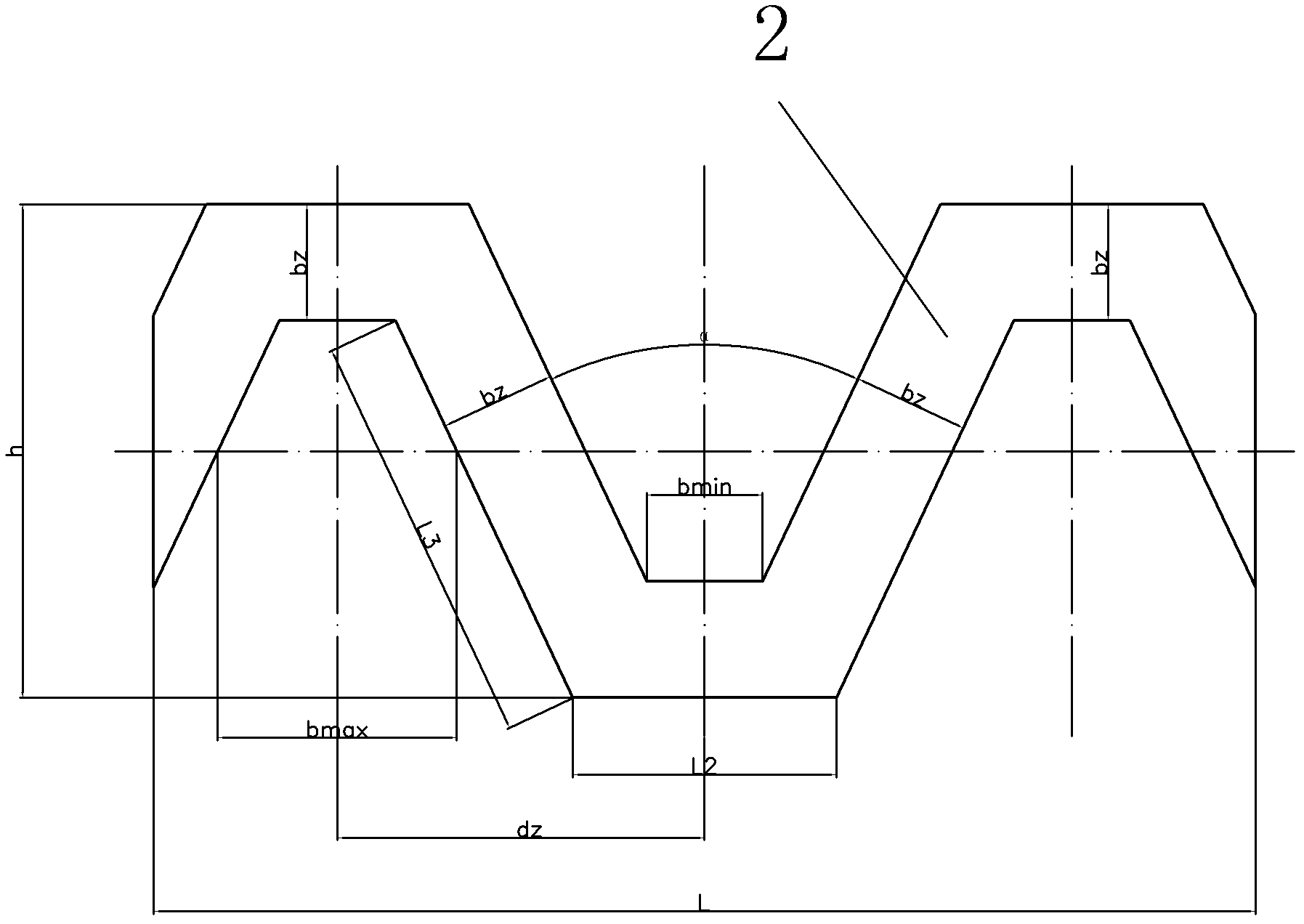
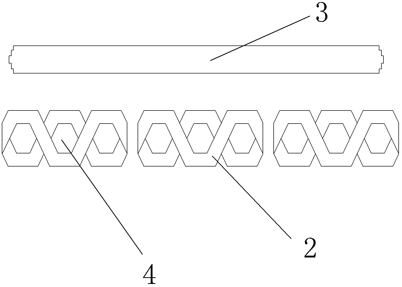
[0032] As shown in the figure, the transformer includes a zigzag winding 1 made of metal. The zigzag winding 1 is formed by connecting a plurality of zigzag metal plates 2 head and tail in turn and superimposed layer by layer, that is, a plurality of metal plates. They are stacked in sequence, and then the head and tail ends of the adjacent metal plates are connected, so that one end of the uppermost metal plate and one end of the lowermost metal plate can be energized, which is equivalent to the "coil" of the transformer. The surface of the meander winding 1 has through holes 4 formed by stacking metal plates 2 , and a magnetic core 3 is inserted into the through holes 4 . The shape of the through hole 4 is the same as that of the magnetic core 3 . Due to the use of metal plates as "coils", the power is greatly increased.

[0033] As a preferred mode of this embodiment...


PUM


Abstract

The invention relates to a transformer. The transformer comprises an interstar winding made of metal, wherein the interstar winding is formed by connecting a plurality of zigzag metal plates sequentially end to end and overlying the metal plates layer by layer; through holes which are formed by overlying the metal plates are formed on the surface of the interstar winding; and magnetic cores are inserted into the through holes. The invention overcomes the defects in the prior art and provides the transformer, which has a simple structure, a good cooling effect, high dissipation, high efficiency, compact structure and high power.

Description

【Technical field】 [0001] The invention relates to a transformer, in particular to a transformer for manufacturing multi-magnetic circuits and multi-stage transformers by means of zigzag windings. 【Background technique】 [0002] A general transformer consists of two important components, namely the magnetic core and the winding. The magnetic core is an intermediate element of electric energy conversion, and its function is to strengthen the magnetic field and improve the efficiency of electromagnetic energy conversion. Windings are divided into input windings and output windings according to their functions. The input winding converts electrical energy into magnetic field energy, and the output winding converts magnetic energy into electrical energy for output. The voltage transformation is realized by the different turns of the input winding and the output winding. [0003] This transformer will have the following shortcomings: [0004] First, because the windings of the e...

Claims


Application Information

Patent Timeline
Patent Type & Authority Applications(China)
IPC IPC(8): H01F27/28
Inventor 王奉瑾
Owner 中山普润斯电源设备技术有限公司
Learn More