Box body of sealing switch cabinet

A switchgear and cabinet technology, applied in the field of sealed switchgear cabinets, can solve the problems of reducing the insulation strength of electrical components in the cabinet, affecting the effect of heat dissipation, and affecting the heat dissipation safety of electrical components in the switchgear, so as to achieve natural heat dissipation and Strong safety, lower temperature inside the cabinet, simple and reasonable structure

Active Publication Date: 2012-02-22
HM POWER (GUANGDONG) CO LTD
View PDF7 Cites 11 Cited by
  • Summary
  • Abstract
  • Description
  • Claims
  • Application Information

AI Technical Summary

Problems solved by technology

The switchgear cabinet of this structure is not a sealed structure in essence, because there are gaps in the connection of each surface, and dust can enter the switchgear through these gaps, affecting the heat dissipation of the electrical components inside the switchgear and the safety of use.
In addition, switch cabinets with the above-mentioned structure generally need to install natural ventilation channel devices to ensure ventilation and heat dissipation inside the cabinet. However, due to the large amount of impurities such as dust in the air outside the cabinet, when the impurities in the air enter the cabinet, it will affect the heat dissipation. Effect, long-term use reduces the insulation strength between electrical components in the cabinet

Method used


Image

  • Box body of sealing switch cabinet
  • Box body of sealing switch cabinet
  • Box body of sealing switch cabinet

Examples


Embodiment Construction

[0014] The present invention will be further described below in conjunction with the accompanying drawings and embodiments.

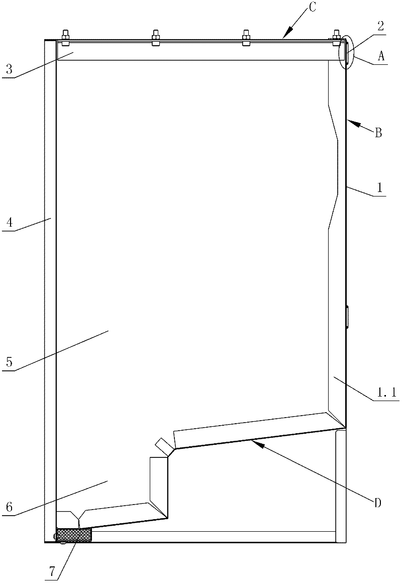
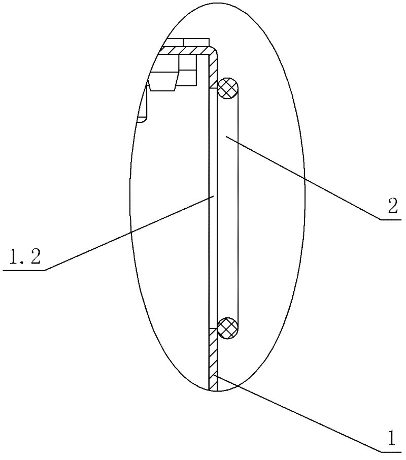
[0015] see Figure 1-Figure 3 , The sealed switchgear box body includes a front sealing plate 1, a side sealing plate 5 and a rear sealing plate 4 which are spliced ​​with each other; the joints between the sealing plates are filled with sealant. The front sealing plate 1 is provided with a rotating shaft hole 1.2, and a sealing ring 2 is provided on the outer periphery of the rotating shaft hole.

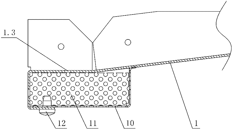
[0016] The front cover 1 is formed by bending the same steel plate, which includes a front B, a top C and a bottom D. There are bent short sides 1.1 on both sides of the front B and the bottom D of the front sealing plate 1, and the bent short sides are closely fixed with the side sealing plates 5 on the left and right sides of the switchgear box through closed rivets. The top surface C of the front sealing plate 1 is closely fixed to the side sealing plat...


PUM


Abstract

The invention discloses a box body of a sealing switch cabinet. The box body comprises a front sealing plate, a side sealing plate and a rear sealing plate which are mutually spliced; joints among the sealing plates are filled and sealed with sealant; the front sealing plate is provided with a rotating axial hole; and a sealing ring is arranged on the periphery of the rotating axial hole. The box body of the switch cabinet, which is disclosed by the invention, is of a framework structure formed by steel plates; the framework structure combines and applies a static seal of the box body and a moving seal of the box body to form a sealing box body of the switch cabinet and ensure air not to enter the interior of the box body from the box body joint and the operation rotating shaft hole, wherein the static seal of the box body is formed by filling and sealing a long-effective sealant for a sheet metal box board; and the moving seal of the box body is formed by splicing the sealing ring with the operation rotating axial hole. In addition, a natural ventilation channel groove is arranged in the box body for enabling electrical elements inside the box body to ventilate and radiate heat; meanwhile, an air cleaning device is arranged at an inlet of an air exchange hole so as to ensure that clean air enters the interior of the cabinet and play a role of reducing the temperature in the cabinet; and the cleanness in the cabinet is ensured and the reduction of insulation strength in the cabinet during long-term operation is reduced.

Description

technical field [0001] The invention relates to a switch cabinet box body, in particular to a sealed switch cabinet box body. Background technique [0002] Chinese Patent Literature No. CN1048300 disclosed on January 2, 1991 that the frame structure of a sealed switchgear cabinet was made of the same frame parts made of angled pieces, and the edges of the angled pieces were bent at right angles to form curved Fold the ends. However, the edges of the corner piece are joined to each other by means of a diagonal (hypotenuse) seal, which provides a seal between the two switchgear panels and forms the corner connection. The flat and bent edges are attached to the frame by means of parts. The switchgear cabinet of this structure is not a sealed structure in essence, because there are gaps in the connection of each surface, and dust can enter the switchgear through these gaps, affecting the heat dissipation of the electrical components inside the switchgear and the safety of use....

Claims


Application Information

Patent Timeline
Patent Type & Authority Applications(China)
IPC IPC(8): H02B1/46F16B5/00
Inventor 李家良麦建国潘国胜
Owner HM POWER (GUANGDONG) CO LTD
Why Eureka
Try Eureka