Special mechanical equipment for machining fan shaft sleeve

A fan shaft and mechanical technology, which is applied in the direction of metal processing machinery parts, metal processing equipment, manufacturing tools, etc., can solve the problems of not meeting market needs, low production efficiency, and easy damage to the surface of workpieces, etc.

Inactive Publication Date: 2013-07-24
SOUTH CHINA UNIV OF TECH +1
View PDF5 Cites 0 Cited by
  • Summary
  • Abstract
  • Description
  • Claims
  • Application Information

AI Technical Summary

Problems solved by technology

[0003] At present, there is no special mechanical device that can integrate the above-mentioned processes in China, so the above-mentioned processes have to be carried out manually. During the processing of the above-mentioned processes, the workpiece is repeatedly clamped, which is very easy to damage the surface of the workpiece, and the production efficiency is low. High product rate, coupled with rising labor costs and other factors, cannot meet the growing market demand
[0004] There are CNC centers for processing such bushings in foreign countries, and all the processes can be completed in one clamping, but because it belongs to a single-line operation, that is, the clamp is fixed, and the processing tools are moved to this position to process the workpiece, and only one process is performed within a period of time work, so the production efficiency is not high

Method used


Image

  • Special mechanical equipment for machining fan shaft sleeve
  • Special mechanical equipment for machining fan shaft sleeve
  • Special mechanical equipment for machining fan shaft sleeve

Examples


Embodiment Construction

[0038] specific implementation

[0039] The present invention will be further described in detail below in conjunction with the embodiments and the accompanying drawings, but the embodiments of the present invention are not limited thereto.

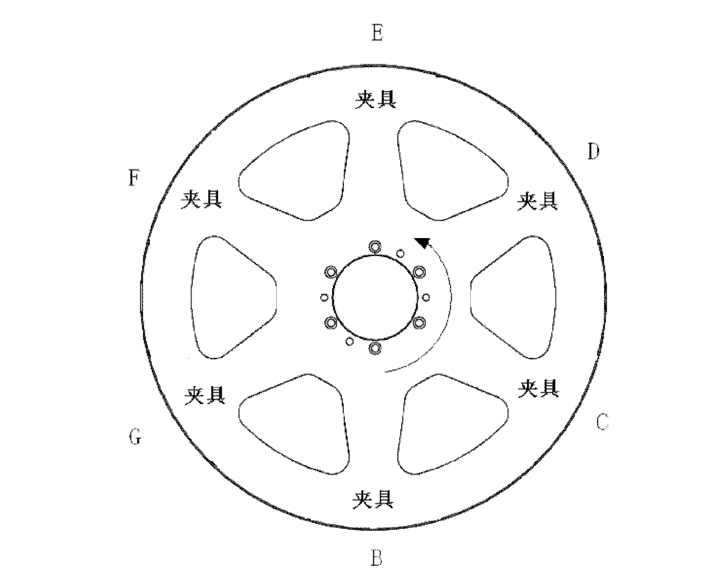
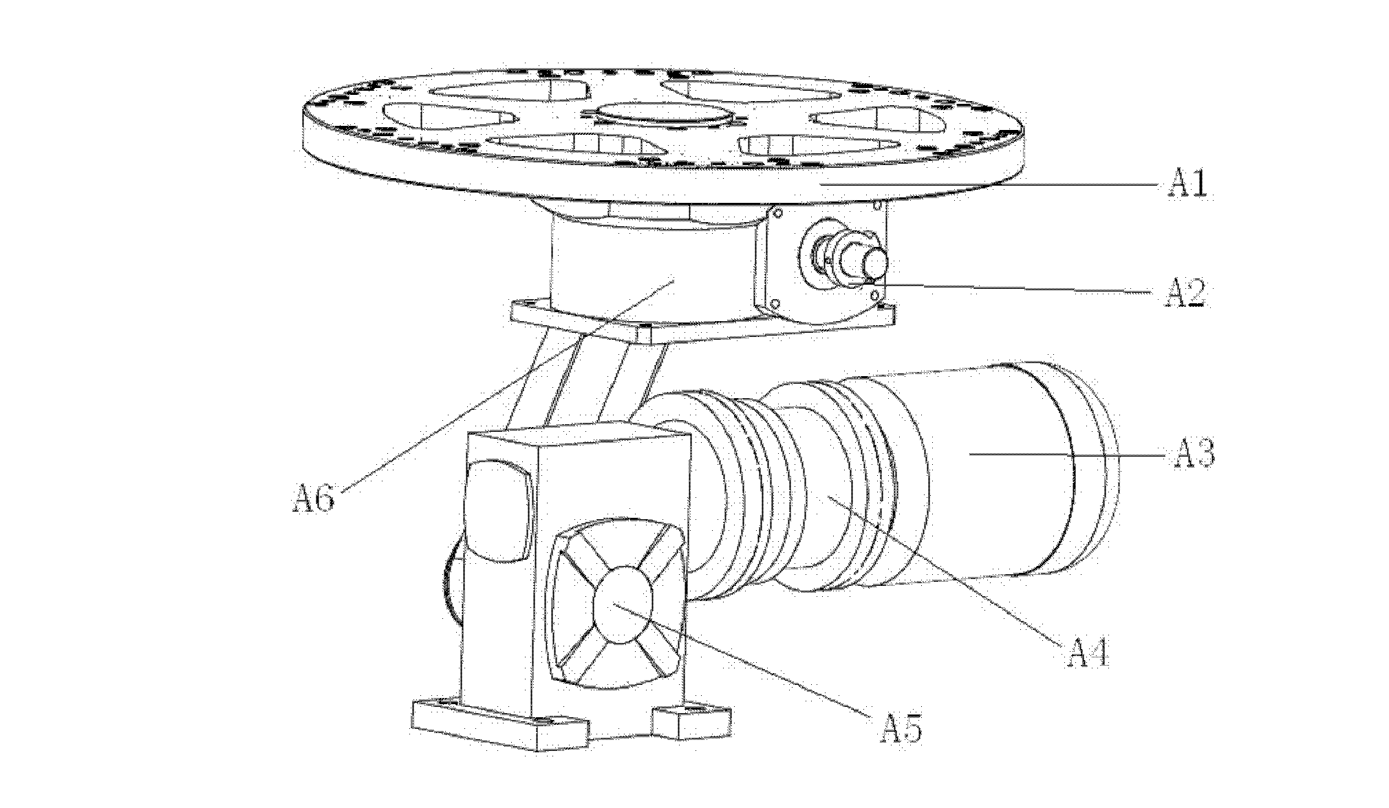
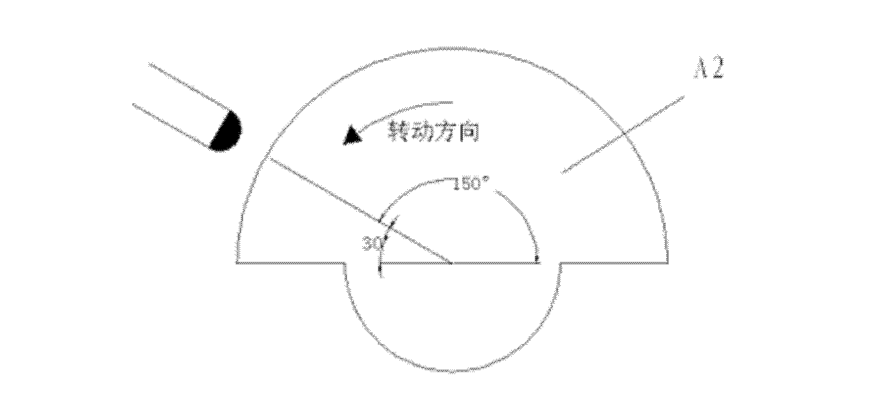
[0040] as attached figure 1 As shown, the special mechanical equipment for fan shaft sleeve processing includes splitter mechanism A, feeding mechanism B, drilling mechanism C, tapping mechanism D, plane milling mechanism E, chamfering and reaming mechanism F, discharging mechanism G, controller , the controller controls the work of other various institutions. What adopt in the present invention is the controller with PLC as the core, and its specific model is Omron CP1E type PLC, CP1W expansion unit.

[0041] Six stations are designed on the workbench of the whole machine, which can process workpieces at the same time. The six stations are distributed counterclockwise as feeding station, drilling station, tapping station, plane millin...


PUM


Abstract

The invention discloses special mechanical equipment for machining a fan shaft sleeve. The mechanical equipment comprises a divider mechanism, a feeding mechanism, a drilling mechanism, a tapping mechanism, a plane milling mechanism, a chamfering and reaming mechanism, a discharge mechanism and a controller. The feeding mechanism, the drilling mechanism, the tapping mechanism, the plane milling mechanism, the chamfering and reaming mechanism and the discharge mechanism are uniformly distributed around the divider mechanism in included angles of 60 degrees; the divider mechanism consists of anindexing disc, a cam, a three-phase motor, an electromagnetic clutch, a reduction box and a high-speed precision intermittent divider; chamfering and reaming in the chamfering and reaming mechanism are implemented on the same station; and the controller is used for controlling the motion of each mechanism. By using the special mechanical equipment for machining the fan shaft sleeve, the production efficiency is greatly improved, the precision of a product is ensured, the defective rate is greatly reduced relative to other machining modes, and the requirement of industrial production is met.

Description

technical field [0001] The invention discloses a shaft sleeve processing device, in particular to a special mechanical equipment for processing a fan shaft sleeve. technical background [0002] The shaft sleeve is one of the commonly used mechanical parts in mechanical equipment. Due to different application occasions, bushings are divided into different types. A shaft sleeve for a fan, such as Figure 9 As shown, it is an indispensable component in air conditioners and other devices. The blank of the shaft sleeve has a height of 20mm, a diameter of the large cylindrical end of 16.2mm, a diameter of the small cylindrical end of 16mm, and a diameter of the inner hole of 8mm; it needs to be drilled, tapped, milled, chamfered, and reamed. The bushing blank is processed into the required workpiece shape, and the machining accuracy error cannot exceed 0.05 mm. [0003] At present, there is no special mechanical device that can integrate the above-mentioned processes in China, ...

Claims


Application Information

Patent Timeline
Patent Type & Authority Patents(China)
IPC IPC(8): B23P23/00B23Q16/02
Inventor 曾敏曾智明
Owner SOUTH CHINA UNIV OF TECH
Why Eureka
Try Eureka