Under-voltage protection device and protection method for circuit breaker
An under-voltage protection and circuit breaker technology, applied in the field of circuit breaker under-voltage protection devices, can solve the problems of non-adjustable voltage value, low accuracy, inability to achieve three-phase simultaneous protection, etc. Effect
- Summary
- Abstract
- Description
- Claims
- Application Information
AI Technical Summary
Problems solved by technology
Method used
Image

Examples
Embodiment Construction
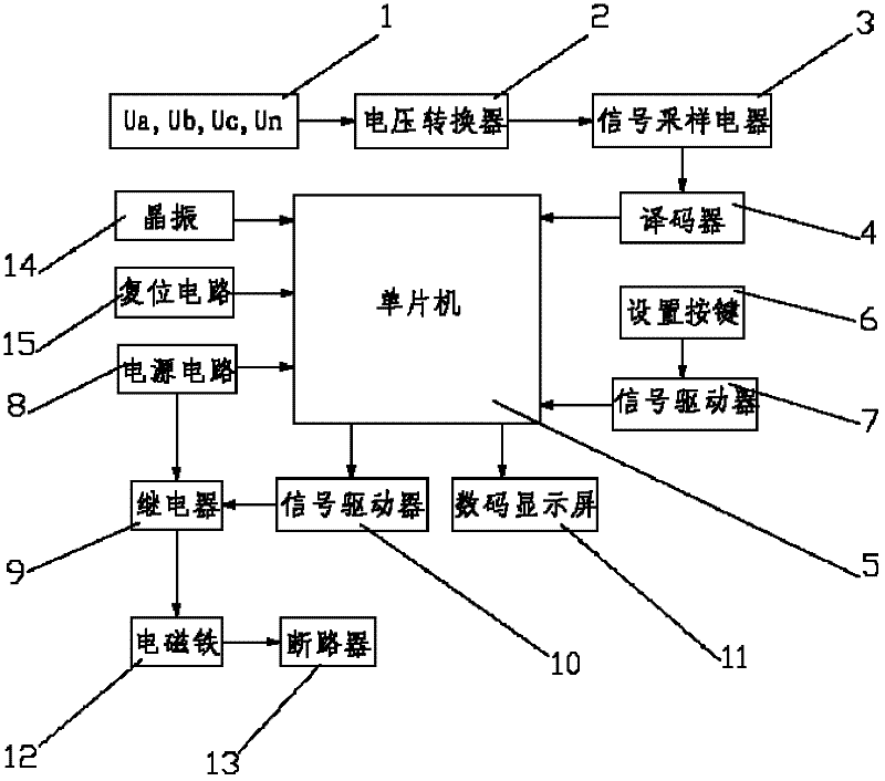
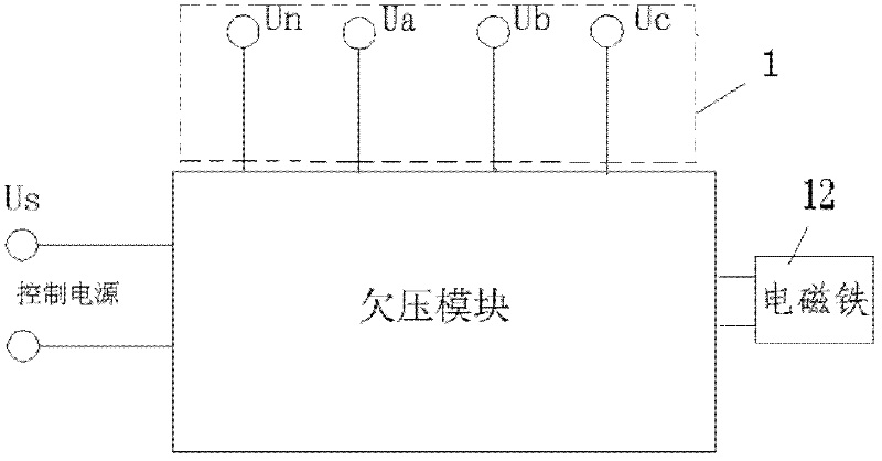
[0025] Such as figure 1 , figure 2 As shown, figure 1 It is a block diagram of the circuit structure of a circuit breaker undervoltage protection device. The undervoltage module is equipped with four voltage input terminals, which are respectively connected to the three-phase alternating current A, B, C, and N on the secondary terminal of the circuit breaker. The voltage of the undervoltage module Input signal Ua, Ub, Uc, Un of the three-phase power supply 1 are connected to the signal sampling circuit 3 via the voltage converter 2, and the output of the signal sampling circuit 3 is connected to the signal input terminal of the single-chip microcomputer 5 via the decoder 4, and the signal of the single-chip microcomputer 5 The output is connected to the signal driver 10, the output of the signal driver 10 is connected to the relay coil 9, the output of the power circuit 8 is connected to the solenoid 12 coil through the normally open contact of the relay 9, and the solenoid 12 i...
PUM
 Abstract
Description
Claims
Application Information
 - R&D
- Intellectual Property
- Life Sciences
- Materials
- Tech Scout
- Unparalleled Data Quality
- Higher Quality Content
- 60% Fewer Hallucinations
Browse by: Latest US Patents, China's latest patents, Technical Efficacy Thesaurus, Application Domain, Technology Topic, Popular Technical Reports.
© 2025 PatSnap. All rights reserved.Legal|Privacy policy|Modern Slavery Act Transparency Statement|Sitemap|About US| Contact US: help@patsnap.com